
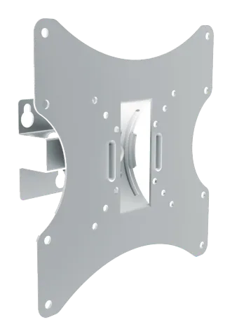
Full Motion LED, LCD TV Wall Mount
Read the entire instruction manual before you start installation and assembly. If you have any questions regarding any of the instructions or warnings, please contact your local distributor for assistance.
Caution: Use with products heavier than the rated weights indicated may result in instability causing possible injury.
- The wall must be capable of supporting the combined weight of the mount and the display, otherwise the structure must be reinforced.
- When mounting to wooden studs, minimum stud thickness of 0.75" (19mm) required.
- Tighten screws firmly, but do not over tighten. Over tightening can cause damage to items, greatly reducing their holding power.
- This product contains small items that could be a choking hazard if swallowed. Keep these items away from children.
- This product is intended for indoor use only. Using this product outdoors could lead to product failure and personal injury.
Note: Ensure you have received all parts according to the component list. If any parts are missing or faulty, telephone your local distributor for assistance. Never use faulty parts.
Note: Check that the bracket is secure and safe to use at regular intervals (at least once every three months).
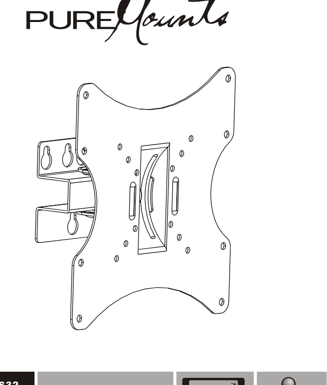
Drawing of the wall mount
PM-LM-TS32
PM-LM-TS32B
PM-LM-TS32W
- 50x50/75x75/100x100
- 200x100/200x200
- 10-42"
- 25-107cm
- 30kg (66lbs) RATED
PureLink GmbH
Von-Liebig-Str. 10 | 48432 Rheine | Germany
Phone: +49 (0) 5971 800 299 0
Note: PureLink GmbH hereby declares that this product complies with Directive 1907/2006/EU and 2011/65/EU.
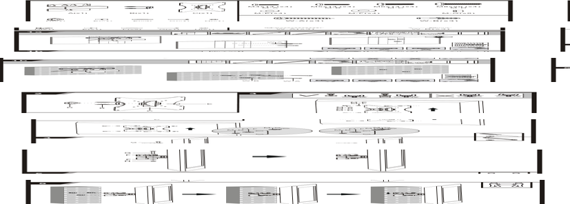
Step 2
Attach bracket part B to plate C using screw D and part E.
Step 3
- Ensure proper order of washers and screws for different mounting configurations.
- M-E, M-F with M-B, M-C, M-D.
- Do not use additional spacers or washers incorrectly.
- Refer to diagram for proper combinations.
Step 4
Attach parts G, F, H to the arm assembly as shown.
Step 5
- Mount the assembly to the wall bracket.
- Use two people for safety.
Legal & Compliance
Product identification
Model: PM-LM-TS32 – manual version 1.0
Warranty and liability
The manufacturer grants the full statutory warranty on all new devices. As the manufacturer has no influence on installation, the warranty only applies to the product itself. If you detect a fault or damage, please contact your dealer and provide your sales slip or invoice as proof of purchase.
The manufacturer is not liable for damage to persons or property caused by improper installation, operation or maintenance not described in this manual. Do not alter or modify the product or its accessories. Any use other than described in this manual is not permitted and voids warranty and guarantee.
Trademarks and disclaimer
Product model and logo are trademarks. All other company and product names mentioned are trademarks of their respective owners. All rights reserved. No part of this publication may be copied or reproduced without prior written permission. We reserve the right to make changes to the device, packaging or manual and accept no liability for misprints.
EU conformity
PureLink GmbH hereby declares that this product complies with Directive 1907/2006/EU and 2011/65/EU.
| Directive / Regulation |
|---|
| 1907/2006/EU |
| 2011/65/EU |
The full text of the EU Declaration of Conformity is available at: www.purelink.de
Packaging
Dispose of packaging separately by material (paper/cardboard, plastics) via the local collection systems. Keep packaging material away from children – risk of suffocation. Packaging register LUCID: DE5958616449295.