
Page 1
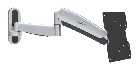
PM-MOVE-37B
ISSUED: SEPT. 2014
INSTALLATION INSTRUCTIONS
Caution: Do not exceed the specified maximum weight as this can cause serious damage.
TV Wall Mount
Maintenance
You should check the tightness of the screws every two months. If you have any doubts regarding installation, please contact your dealer or our customer service.
Page 2
Note: Please read the entire installation manual carefully before you begin assembly and installation.
CAUTION
- Do not start installing your device before reading the installation instructions and understanding the contained directions and warnings. If you have any questions, please contact your local dealer.
- Please adhere to the manufacturer’s recommended wall clearance to avoid potential damage.
- This product should only be installed by someone with good craftsmanship skills, basic construction experience, and who fully understands the instructions.
- Please ensure the wall is capable of safely supporting the total weight of the mount along with all attached components.
- Never exceed the allowed maximum weight.
- When mounting on walls with wood paneling or stud walls, ensure the screws are anchored in the center of the cross studs. Use a stud detector if necessary.
- Do not lift or position heavy equipment alone; do so with a second person or mechanical assistance.
- Tighten the screws firmly but do not overtighten. Over-tightening can damage components and compromise the mounting.
- This product is intended for indoor use in your home. Outdoor use may cause damage and injuries.
Component Checklist
IMPORTANT: Make sure you have received all components by comparing the delivery with the component checklist. If parts are missing or defective, please contact your dealer for replacement.
- Joint Arm A (x1)
- Wrench D (x1)
- 4mm Allen Key B (x1)
- 6mm Allen Key B (x1)
- Pack M
- Pack W
- D8 Washer (x4) M-F
- D (x4)
- M-E
- 5 Washer small spacer M-G (x8)
- Concrete Anchor W-B (x3)
Page 3
1. Removing the VESA Plate from the Wall Mount
2. Removing the Cover Plates
- Loosen the upper nuts
- Then remove the lower nuts Remove the VESA plate
3a. Mounting on a Stud Wall or Wood Paneling
- Locate and mark the exact position of the mounting holes.
- Drill the holes.
- Screw the wall mount onto the wall.
Caution: Ensure that the screws are anchored in the center of the cross studs. Use a stud detector if necessary. For other wall types, the installer is responsible for sourcing the correct installation materials (anchors, screws, etc.). Please ensure the wall is capable of safely supporting the total weight of the mount along with all attached components.
Page 4
3b. Mounting on Solid Brick and Concrete Walls
- Locate and mark the exact position of the mounting holes.
- Drill the holes.
- Screw the wall mount onto the wall.
Please ensure the wall is capable of safely supporting the total weight of the mount along with all attached components.
4. Attaching the Decorative Covers
5. Mounting the VESA Plate
Top of the TV
Page 5
Tighten all screws firmly, but do not overtighten them.
Note: Select the appropriate screws, washers, and spacers (if required) based on the type of display.
- Screw the appropriate spacers onto your TV device
6. Installation of the Display
- Loosen the upper nuts until approximately 4mm clearance to the wall mounting plate is achieved.
- Hang your TV onto the wall mount.
- Align your TV as desired.
- Now attach the lower nuts and tighten all nuts.
Page 6
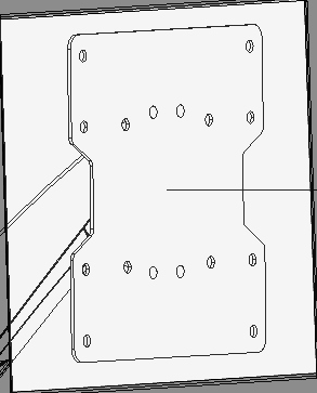
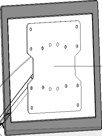
7. Adjusting Tension 9. Adjustment
8. Cable Management
Please tighten the inner adjustment screw if creaking noises occur during use.
Tighten the screws / nuts with the Allen key (or tighten the nuts) until the tilt angle can be fixed.
Keep the arm height constant while adjusting the screw. Use the supplied Allen key to loosen or tighten the swivel arm tension according to your screen's weight.
- If the screen lowers by itself without touch: Turn the screw towards + to increase tension.
- If the screen rises by itself without touch: Turn the screw towards - to decrease tension.
Connect the cables to your TV device. Route the cables along the swivel arms and press the cables into the corresponding cavities to hold them in place.
Note: Allow the cables to hang slightly to avoid restricting the swivel arm’s movement range.
height adjustable
Set desired position and tilt angle.
Legal & Compliance
Product identification
Model: PM-MOVE-37B – manual version 1.0
Warranty and liability
The manufacturer grants the full statutory warranty on all new devices. As the manufacturer has no influence on installation, the warranty only applies to the product itself. If you detect a fault or damage, please contact your dealer and provide your sales slip or invoice as proof of purchase.
The manufacturer is not liable for damage to persons or property caused by improper installation, operation or maintenance not described in this manual. Do not alter or modify the product or its accessories. Any use other than described in this manual is not permitted and voids warranty and guarantee.
Trademarks and disclaimer
Product model and logo are trademarks. All other company and product names mentioned are trademarks of their respective owners. All rights reserved. No part of this publication may be copied or reproduced without prior written permission. We reserve the right to make changes to the device, packaging or manual and accept no liability for misprints.
Packaging
Dispose of packaging separately by material (paper/cardboard, plastics) via the local collection systems. Keep packaging material away from children – risk of suffocation. Packaging register LUCID: DE5958616449295.