
Contents, Glossary of terms
Glossary of terms
Audio Return Channel (ARC) ARC enables audio from a display to be extracted over HDMI.
HDBaseT Technology used to convert HDMI into a format which can be carried over network cable.
IR RX & IR TX
Infrared (IR) Receiver (RX) and Transmitter (TX). The RX ‘receives’ a signal from another remote control and the TX ‘transmits’ it. (See page 12)
Tipping Point Compression (TPC)
Video content such as Ultra HD 4K 60 4:4:4 uses up to 18Gbps of data at any one time which is not possible over current HDBaseT technology. HDA makes transmission of 18Gbps content possible using TPC. Visually lossless, TPC only becomes active if HDBaseT’s threshold is breached, hence the term tipping point.
XTND transmitter Part of the XTND pair. The XTND transmitter takes a HDMI signal and converts it into HDBaseT. The transmitter is installed at the source end of the setup.
XTND receiver Part of the XTND pair. The XTND receiver takes the HDBaseT signal made by the XTND transmitter and converts it back to HDMI so that it can be connected to a display.
In the box, Features
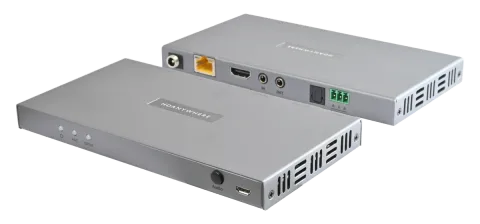
- x1 XTND 4K (40) with ARC & TPC Transmitter
- x1 XTND 4K (40) with ARC & TPC Receiver
- x2 Infrared Transmitter cable (1.5m) (IR TX)
- x2 Infrared (20-60Khz) Receiver cable (1.5m) (IR RX)
- x1 24V 1A Power Supply with adapters (UK,EU,US,AU)
- x2 Three-Pin Phoenix Connector
- x4 Mounting Brackets
- x1 User Manual
Name: XTND 4K (40) with ARC & TPC
Product code: XTND4K402ARCTPC
In the box
Note: For optimum performance and safety, please read these instructions carefully before connecting, operating or configuring this product.
Please keep this manual for future reference.
Tip: Surge protection is recommended
This device contains sensitive electrical components that may be damaged by electrical spikes, surges, electric shock, lightning strikes, etc. The usage of surge protection systems is recommended in order to protect and extend the life of your system.
Features
- Supports video picture formats up to 4K@60Hz (4:4:4) including HDR and Dolby Vision (4K@30Hz)
- Supports 18Gbps bandwidth
- 4K up to 40m (131ft)
- Digital audio support up to and including Dolby Atmos and DTS:X
- Audio extraction over stereo or SPDIF.
- ARC (Output on XTND Transmitter SPDIF)
- Bi-directional IR & RS232
- CEC
- Bi-directional Power over HDBaseT (PoH)
Specifications
| Specification | Value |
|---|---|
| HDMI version | HDMI 2.0b |
| HDCP compliance | HDCP 2.2 & HDCP 1.4 |
| Video bandwidth | 18Gbps |
| Video resolution | Up to 4K@60Hz (4:4:4) with HDR |
| Colour space | RGB, YCbCr 4:4:4, YUV 4:4:4, YCbCr 4:2:2/4:2:0 |
| Colour depth | 8-bit, 10-bit, 12-bit (1080p@60Hz) 8-bit (4K@60Hz) |
| HDR formats | HDR10, HDR10+, Dolby Vision, HLG (4K@30Hz) |
| Video & audio I/O | Input: x1 HDMI, x1 SPDIF Outputs: x1 HDMI, x1 3.5mm Stereo Jack, x1 SPDIF |
| Transmission distance | 1080p 70m (230ft) 4K 40m (131ft) |
| HDMI audio formats | PCM 2.0 / 5.1 / 7.1, Dolby Digital / Plus / EX / True HD / Atmos, DTS, DTS-EX, DTS-96 / 24, DTS High Res, DTS-HD Master Audio, DTS-X |
| Stereo audio formats | PCM 2.0 |
| SPDIF audio formats | PCM 2.0, Dolby Digital / Plus, DTS |
| Infrared | 20Khz - 60Khz |
| ESD protection | ±8kV (Air-gap discharge) ±4kV (Contact discharge) |
| Power consumption | 11.5W (Maximum) |
| Power supply | 24V 1A |
| Operating temperature | 0°C - 40°C / 32°F - 104°F |
| Storage temperature | -20°C - 60°C / -4°F - 140°F |
| Relative humidity | 20 - 90% (Non-condensing) |
| Housing | Aluminium |
| Colour | Grey (Carbonite) |
| Dimensions (W/D/H) mm | Transmitter: 165 x 88 x 16 Receiver: 165 x 88 x 16 |
| Weight | Transmitter: 120g Receiver: 120g |
| Package weight | 1100g |
XTND 4K (40) ARC & TPC transmitter port description
DC24VRS232 HDMI (IN)IRSPDIF/Stereo OUT) ) Video
ARC
IN OUT A B
SPDIF Audio
Transmitter rear and front panel ports
Help is only a n email a w a y : support@hdanywhere.com.
Transmitter Diagram
Description
- Power: Indicator light. If this light is on and solid then the XTND transmitter has power.
- ARC: Indicator light meaning that ARC audio is being requested from the display.
- SPDIF: Indicator light meaning that audio from the XTND receiver “SPDIF/Stereo (IN)” port is being routed to the XTND transmitter.
- Audio: Sets the audio mode for XTND described by indicator lights #2 & #3. If both ARC and SPDIF lights are off then audio is being extracted at the HDMI source.
- Firmware: Micro USB port to update XTND firmware.
- RS232: Connect the three-pin phoenix connector to this port to send RS232 commands to the XTND receiver or vice-versa.
- SPDIF / Stereo (OUT): Outputs 2ch stereo or multichannel optical audio output.
- IR (IN) / (OUT): Connect an IR TX to the “IR OUT” to enable remote (IR) control of any AV device local to the XTND transmitter. Connect an IR RX to the “IR IN” port to receive an IR command from a remote control to pass through to the XTND receiver.
- HDMI (IN): HDMI video input. This port does not output ARC audio returned from the display or the XTND receiver.
- VIDEO TPC: HDBaseT (RJ45) video output port. 18Gbps video will pass through using TPC. The HDBaseT port has two indicator lights. Left light: solid means connection between XTND transmitter and XTND receiver is good. Flashing means that the connection is poor. Off means that there is no connection detected. Right light: solid means HDCP is detected. Flashing means there is no HDCP. Off means no HDMI signal is detected.
- DC24V: Connect the supplied power supply to this port to provide power to the XTND transmitter and receiver.
XTND 4K (40) ARC & TPC receiver port description
DC24VHDMI (OUT)IRRS232 Video
ARC
IN OUT A B
SPDIF
SPDIF IN ) )
Audio
Receiver rear and front panel ports
Receiver Diagram
Description
- Power: Indicator light. If this light is on and solid then the XTND receiver has power.
- ARC: Indicator light meaning that ARC audio is being requested from the display.
- SPDIF: Indicator light meaning that audio from the XTND receiver “SPDIF/Stereo (IN)” port is being routed to the XTND transmitter.
- Audio: Sets the audio mode for XTND described by indicator lights #2 & #3. If both ARC and SPDIF lights are off then audio is being extracted at the HDMI source.
- Firmware: Micro USB port to update XTND firmware.
- RS232: Connect the three-pin phoenix connector to this port to send RS232 commands to the XTND transmitter or vice-versa.
- SPDIF (IN): For displays that do not support ARC, you can extract audio via SPDIF from the display to this port.
- IR (IN) / (OUT): Connect an IR TX to the “IR OUT” to enable remote (IR) control of a display local to the XTND receiver. Connect an IR RX to the “IR IN” port to receive an IR command from a remote control to pass through to the XTND transmitter.
- HDMI (OUT): HDMI video output. Connect to your display to provide a picture.
- VIDEO TPC: HDBaseT (RJ45) video output port. 18Gbps video will pass through using TPC. The HDBaseT port has two indicator lights. Left light: solid means connection between XTND transmitter and XTND receiver is good. Flashing means that the connection is poor. Off means that there is no connection detected. Right light: solid means HDCP is detected. Flashing means there is no HDCP. Off means no HDMI signal is detected.
- DC24V: Connect the supplied power supply to this port to provide power to the XTND receiver and transmitter.
IR (Infrared) control, Testing IR works
XTND can send IR signals bi-directionally between the transmitter and receiver to control almost any AV device. Using this feature will allow you to use a remote control at either end of the XTND setup and pass that IR command from your display location back to the XTND transmitter or vice-versa.
Sending IR commands from a display ‘back’ to the XTND transmitter
To send commands in the other direction (from the source / XTND transmitter) to a display, simply follow the process above but swap any instance of an XTND transmitter with a XTND receiver.
- Connect an IR TX to port labelled “IR (OUT)” on the XTND transmitter.
- Place the IR TX bud (small tear drop part) in front of the IR window of the device that you wish to control.
- Connect an IR RX to port labelled “IR (IN)” on the XTND receiver.
- Place IR RX in line-of-sight of the remote control.
IR Transmitter (IR TX)
IR Receiver (IR RX)
1.5m
Testing that IR works
This section aims to verify that your XTND’s IR control system is setup correctly and assumes that all other setup has been followed as per the instructions laid out in this manual. Please refer to the XTND wiring diagrams in this document to ensure that your setup matches that before proceeding with the verification below.
Testing operation from a display ‘back’ to the XTND transmitter
Start this test by ensuring that your XTND system is powered on and your source device (connected to your XTND transmitter) is being correctly displayed on screen. Check that your IR cabling is correctly connected to your XTND system (page 12) and that your remote control has a clear line-of-sight to the IR RX. Point your remote at the IR RX and test a remote control command for your source device. You should notice that it responds as if the source device was directly in front of you. If it worked then you have setup IR control correctly. Repeat this step at the XTND transmitter end to confirm control over displays.
Cabling
Currently you can use Cat6, Cat6e, Cat6a, Cat7 or Cat7a with XTND. Cat5e may work, but is not recommended, due to its limited bandwidth capabilities.
Optimum performance
Whichever network cable type you choose, ensure that the main wiring architecture is ‘solid core’ and not stranded ‘patch’ cabling. Patch cabling can be used for the last few metres of a run (e.g wallplate) but should be avoided over longer runs as signal transfer over stranded cores is significantly impacted. The use of pre-made leads is not recommended unless you can be absolutely sure of their construction credentials (i.e. solid core 568B). For optimum performance, use a single piece of Cat cable terminated directly at the transmitter and the receiver ends. Make sure to use the correct connector types (i.e. RJ45 solid core) crimp connectors.
Shielded cables
Shielded FTP cable is not a stipulation. However, if you are using this type of cable ensure compatible shielded accessories are used. Failure to terminate cable screen at all points can induce interference rather than eliminate it.
Patch panels and wall plates
If patch panels are terminated correctly then there is a minimal loss of distance. The use of wallplates and patch panels has the potential to cause increased resistance on the cable introducing pinch points for signal transmission and could reduce transmission lengths.
Tip: Instead of using RJ45 wallplates use brush plates.
HDMI cabling
HDANYWHERE recommends using suitably robust and good quality HDMI cables. It is not advised to use passive HDMI cables over 5 metres in length either on the inputs or the outputs of the XTND system. Where HDMI cables longer than 5 metres are required, HDA recommends utilising its own brand of long distance HDMI cables or a suitable alternative.

Terminate using RJ45 connectors to 568B wiring standard.
1 2 3 4 5 6 7 8
12345678
Caution: DO NOT USE ANY COPPER CLAD ALUMINIUM (CCA) Cat 6/7 CABLE.
Note: Watch online! https://youtu.be/EbWAEndiCuU
Example wiring diagram & explanation

Help is only an email away: support@hdanywhere.com.
Example wiring diagram
We have detailed a setup to show how the main feature-set of this XTND system could be used and demonstrated together.
Diagram 1
In this diagram, an Apple TV is being controlled by a native Apple TV remote control from the display location. IR commands sent from the display location are then reproduced back at the source (XTND transmitter) end providing distance remote control of the device in question.
Audio is being dynamically extracted from the display using ARC. This is carried from the display back to the XTND transmitter and then output via the SPDIF port feeding the AVR with audio.
- HDMI Cable
- Ethernet Cable
- Optical Cable
- HDBaseT
- IR RX/TX Cable
- Speaker Cable
Diagram 1.
Diagram 2
Note: This XTND system has been designed so that it can be installed in multiple ways. The purpose of the diagram is to illustrate a typical/example setup and assumes that you are already familiar with the basics of wiring and infrastructure. If you are unsure how you might install this device in to your property then contact support@hdanywhere.com or contact a HDA Pro (https://hdanywhere.com/dealers-and-installers/) for further assistance.
This diagram describes how XTND can be used to control displays from the source (XTND transmitter) end. Ideal for hospitality or commercial applications. Here, the XTND system is being used to extend the range of an Apple TV. As the display is a projector there is no ARC but audio is being extracted at the source and output via the SPDIF port feeding the AVR with audio.
- HDMI Cable
- Ethernet Cable
- 3.5mm Stereo
- HDBaseT
- IR RX/TX Cable
- Speaker Cable
Diagram 2.
Power up sequence
- Ensure that all devices are turned off.
- Connect HDMI source to “HDMI (IN)” port on the XTND transmitter.
- Connect the XTND transmitter and receiver together by using Cat 6/7 cable connected to the each end of the “Video TPC” port.
- Connect a display to the “HDMI (OUT)” port on the XTND receiver.
- If any devices require IR control, ensure that IR is connected at this stage as well (page 12).
- Plug in the supplied power lead in either the transmitter or receiver location. XTND will automatically power on. XTND power indicator LEDs should be lit and solid.
- Turn on the source device followed by the display.
- Ensure that your display is set to the correct AV channel.
- A picture should now be displayed.
- give us notice in writing of your intention to claim under the guarantee during the Guarantee Period, and do so within a reasonable time after finding that some or all of the Products do not comply with the guarantee set out in paragraph 2;
- show that the Products that you claim are defective, have been examined by a HDA Pro or other authorised or suitably qualified installer, and that they have confirmed in writing that the suspected defect in the Products stems solely from a fault in the HDA hardware;
- give us a reasonable opportunity to examine the Products in question;
- provide us with an order number and a dated sales or delivery receipt from an HDA Distributor, HDA Pro or other authorised dealer, reseller or installer of the Products.
- obtain from us in advance of returning the Products a return merchandise authorisation and/or case number;
- (if asked to do so by us) return such Products to our place of business at our cost.
Circumstances where your guarantee doesn’t apply
- If you make any further use of the Products after giving us notice of an issue in accordance with paragraph 5;
- the defect arises because you failed to follow our oral or written instructions as to the storage, installation, use and maintenance of the Products;
- the defect arises as a result of your use of the Products with any other software or hardware that is not compatible with the Products;
- the products are used by you for any commercial purpose, including rental or demonstrative purposes;
- you alter or repair the Products without the written consent of HDA;
- the defect arises as a result of an act of god, fair wear and tear, or your misuse, abuse, unreasonable use, wilful damage, negligence, or abnormal storage of the Products or by any other causes unrelated to defective hardware or manufacturing;
- where the serial number has been altered, defaced or removed;
- where the warranty seal on the system has been altered, defaced or removed; or
- where the Products differ from their description as a result of changes made to ensure they comply with applicable statutory or regulatory requirements.
Transferring your guarantee to someone else
HDA will not accept any liability under such guarantee unless you are the original customer or can produce a letter or chain of letters from the original customer and subsequent customers (where appropriate) transferring the benefit of the guarantee to you.
Products that are not covered by this guarantee
This guarantee does not cover products sold and clearly marked “as is”, “B-grade”, or with faults. This guarantee does not apply to any system software that is preinstalled in the HDA hardware, or is subsequently provided via update or upgrade releases. Any and all HDA software is licensed to you under the terms of a separate end user licence agreement found here: https://hdanywhere.com/legals
How this guarantee works with our EULA
We may void this guarantee if we reasonably believe that the HDA system has been used in a manner that violates terms of our separate End User Licence Agreement (EULA) for the HDA software. You assume all-risk and liabilities associated with the use of third party products in conjunction with the Products.
Your statutory rights
This guarantee is in addition to your statutory rights (including under the Consumer Rights Act) which are not affected by this guarantee.
General terms of this guarantee
- Except as provided in this guarantee, we shall have no liability to you in respect of the Products’ failure to comply with the guarantee set out in paragraph 2.
- We reserve the right to amend or withdraw this guarantee at any time although for the avoidance of doubt any guarantees that are in existence at such a time will be honoured.
- These Conditions shall apply to any repaired or replacement Product supplied by us.
Guarantee contact information
To contact (support@hdanywhere.com) or call HDANYWHERE Technical Support (call charges will depend on your telephone provider. Please check with your operator for exact charges). The team is available 9am - 5pm weekdays. To help us handle your query promptly, please have your invoice number and model SKU and serial ready.
EU Conformity
Hereby, HDANYWHERE declares that this HDMI connectivity device is in compliance with the essential requirements and other relevant provisions of the following Directives: 2006/95/EC (LVD Directive); 2004/108/EC (EMC Directive); 1999/5/EC (R&TTE Directive). The full text of the EU declaration of conformity is available in the compliance section at HDANYWHERE.com/legals
Recycling your device properly
In some areas, the disposal of certain electronic devices is regulated. Make sure you dispose of or recycle your device in accordance with your local laws and regulations.
Important information
Let us know what you think.
We would love to hear how we could further improve our products and services.
If we can make something better, please let us know!
support@hdanywhere.com
Copyright © HDANYWHERE.
HDANYWHERETM is a trading name of HD Connectivity Ltd.
Registered in England & Wales 06046737 VAT 913222367
Note: HDANYWHERE assumes no responsibility for any inaccuracies that may be contained in this document. In no event will HDANYWHERE be liable for direct, indirect, special, incidental, or consequential damages resulting from any defect or omission in this document, even if advised of the possibility of such damages.
Legal & Compliance
Product identification
Model: HDA-250885 – manual version 1.0
Trademarks and disclaimer
Product model and logo are trademarks. All other company and product names mentioned are trademarks of their respective owners. All rights reserved. No part of this publication may be copied or reproduced without prior written permission. We reserve the right to make changes to the device, packaging or manual and accept no liability for misprints.
WEEE reg. no.: DE 93847290
Packaging
Dispose of packaging separately by material (paper/cardboard, plastics) via the local collection systems. Keep packaging material away from children – risk of suffocation. Packaging register LUCID: DE5958616449295.