
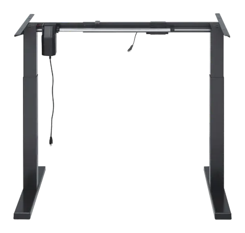
Assembling the Crossbar
Checklist and Installation
- A (x1) Crossbar
- B (x1) Lifting Column
- C (x1) Lifting Column
- D (x1) Crossbar Spacer
- E (x2) Side Bracket
- F (x1) Sync Rod
- G (x2) Foot

- H (x1) Adapter Holder
- I (x1) AC Adapter
- J (x1) Power Plug
- K (x1) Controller
Note: The picture of the controller is for your reference only. Actual product may vary.
This page can be torn out so that it's easier for you to match the components with the images.
- S-A (x16) Hex Head Screw
- S-B (x10) Phillips Head Screw + 1 Spacer
- S-C (x2) Phillips Head Screw
- S-D (x3) Cable Clip
- S-E (x10) Anti-Vibration Pad
- S-F (x1) Allen Wrench
Now let's start the installation.
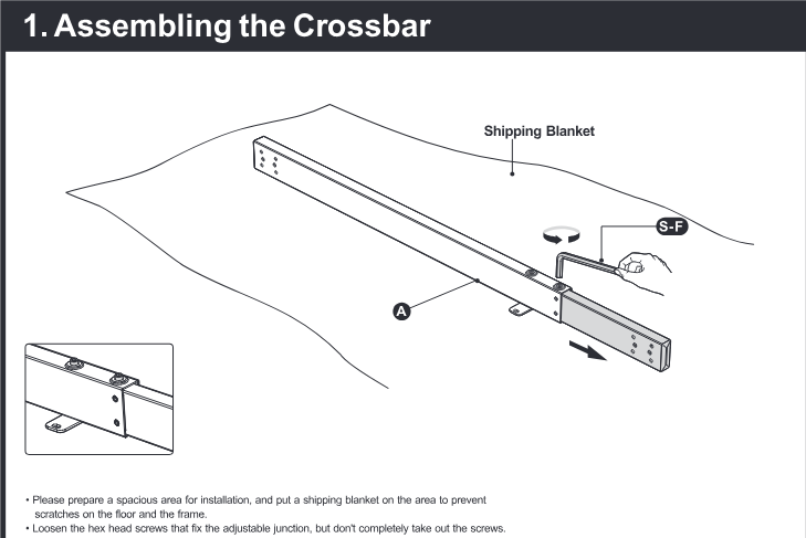
- Please prepare a spacious area for installation, and put a shipping blanket on the area to prevent scratches on the floor and the frame.
- Loosen the hex head screws that fix the adjustable junction, but don’t completely take out the screws.
Note: The drawing of the crossbar is the backside of it.
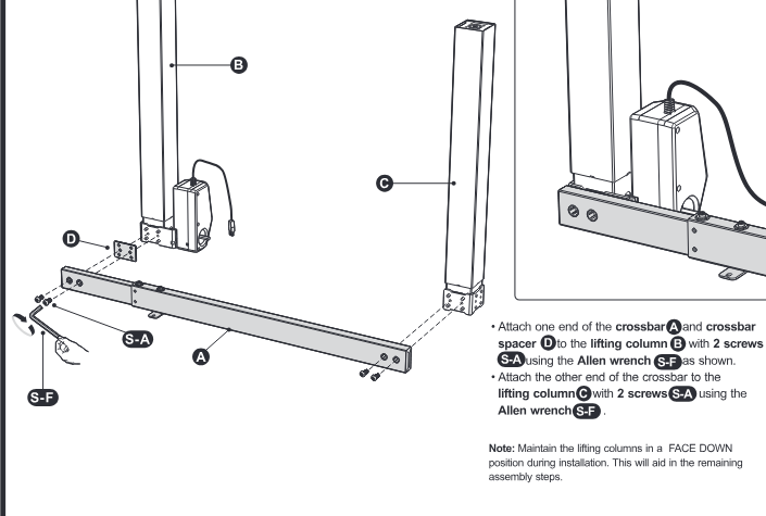
- Attach one end of the crossbar A and crossbar spacer D to lifting column B with 2 screws S-A using the Allen wrench S-F as shown.
- Attach the other end of the crossbar to the lifting column C with 2 screws S-A using the Allen wrench S-F.
Note: Maintain the lifting columns in a FACE DOWN position during installation. This will aid in the remaining assembly steps.
Installing the Side Brackets
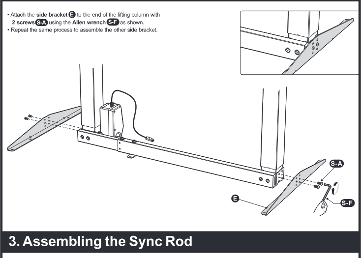
- Attach the side bracket (B) to the end of the lifting column with 2 screws (S-A) using the Allen wrench (S-F) as shown.
- Repeat the same process to assemble the other side bracket.

Assembling the Sync Rod
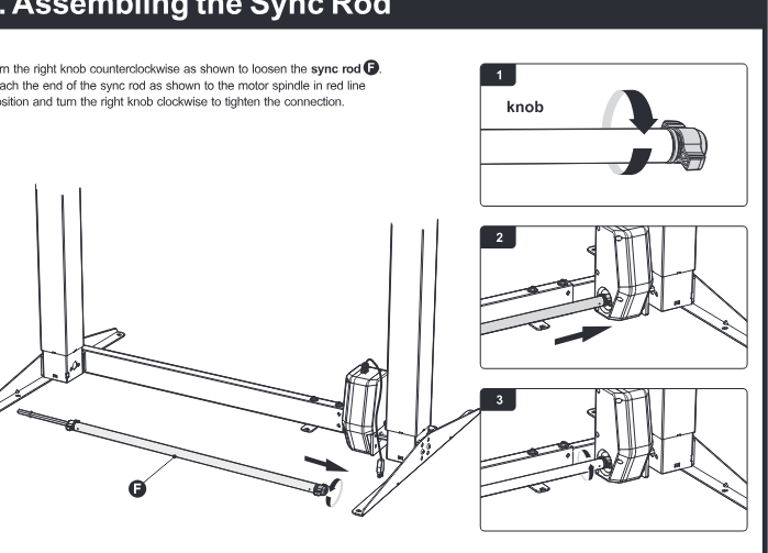
- Turn the right knob counterclockwise as shown to loosen the sync rod (E).
- Attach the end of the sync rod as shown to the motor spindle in red line position and turn the right knob clockwise to tighten the connection.
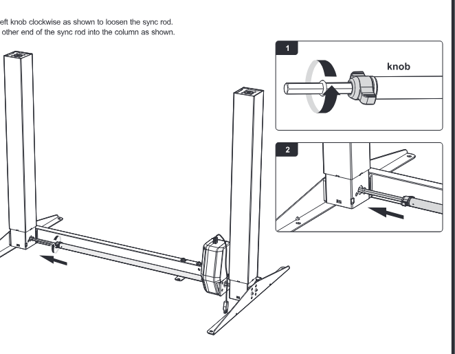
- Turn the left knob clockwise as shown to loosen the sync rod.
- Insert the other end of the sync rod into the column as shown.
- Place the assembled frame on the back of the desktop as shown and then adjust the width of the crossbar to suit the size of the desktop.
- Tighten all the hex head screws on the crossbar to finish the adjustment.
- Re-tighten the sync rod by turning the knob counterclockwise as shown.
- After tightening the screws, use a drill to make mounting holes on the backside of the desktop through the 10 mounting holes on the side brackets.
Note: The depth of the mounting holes should be over 10mm and the diameter should be less than 3mm.
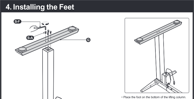
Installing the Feet
- Place the foot on the bottom of the lifting column.
- Align the mounting holes on the foot with the screw holes on the lifting column.
- Fix the foot (G) with 4 screws (S-A) using the Allen wrench (S-F).
- Repeat the same process to assemble the other foot.
Assembling the Adapter Holder
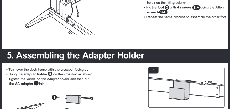
- Turn over the desk frame with the crossbar facing up.
- Hang the adapter holder (H) on the crossbar as shown.
- Tighten the knobs on the adapter holder and then put the AC adapter (I) into it.
Connecting Cords and Attaching the AC Adapter
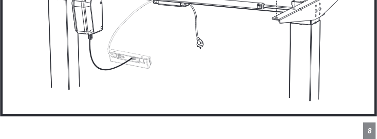
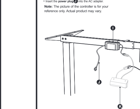
- Connect the controller (J) with the AC adapter (I) and motor as shown.
- Insert the power plug (K) into the AC adapter.
Note: The picture of the controller is for your reference only. Actual product may vary.
Assembling the Desktop
- Attach the anti-vibration pad (S-E) to the surface of the crossbar on the ten positions as shown.
- Turn over the desk frame with the crossbar facing down.
- Align the previously drilled screw holes with the mounting holes on the crossbar. Insert and tighten the 10 screws S-B from below.
- Attach the controller to the desktop with 2 screws S-C using a driller.
- Stick the adhesive cable clip S-D under desk to organize cords.
1
2
Level Adjustment
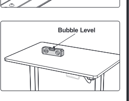
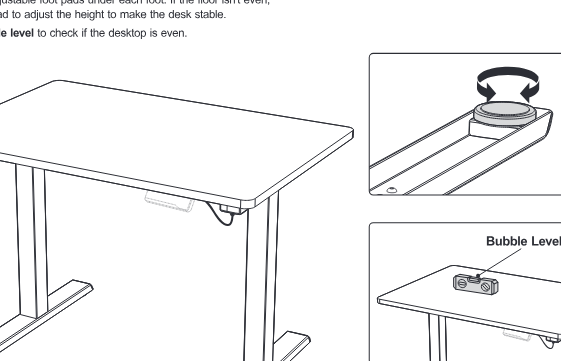
There are two adjustable foot pads under each foot. If the floor isn’t even, simply turn the pad to adjust the height to make the desk stable.
Tip: Use a bubble level to check if the desktop is even.
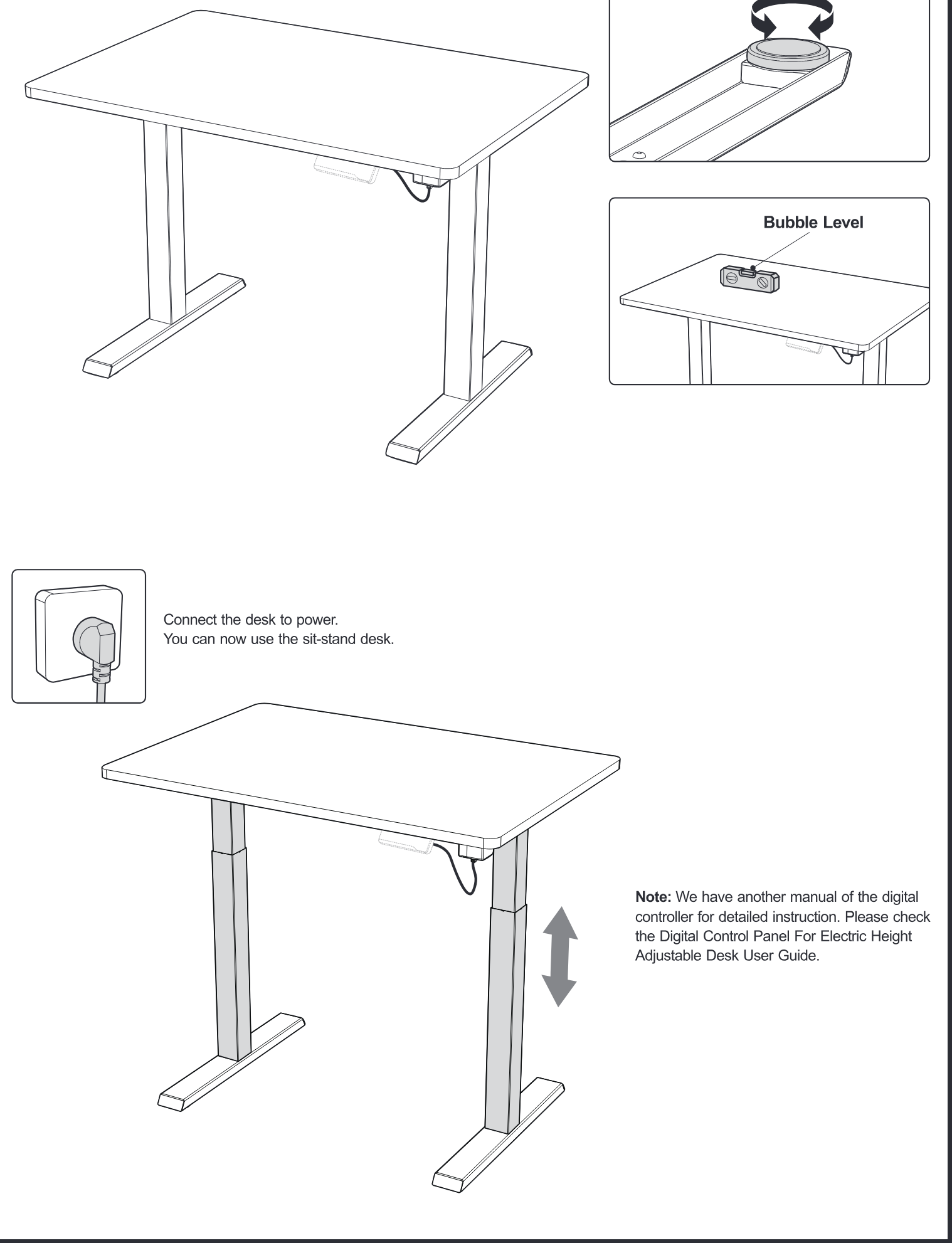
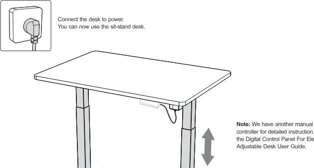
Connect the desk to power. You can now use the sit-stand desk.
Note: We have another manual of the digital controller for detailed instruction. Please check the Digital Control Panel For Electric Height Adjustable Desk User Guide.
Legal & Compliance
Product identification
Model: PM-DESK-00 – manual version 1.0
Warranty and liability
The manufacturer grants the full statutory warranty on all new devices. As the manufacturer has no influence on installation, the warranty only applies to the product itself. If you detect a fault or damage, please contact your dealer and provide your sales slip or invoice as proof of purchase.
The manufacturer is not liable for damage to persons or property caused by improper installation, operation or maintenance not described in this manual. Do not alter or modify the product or its accessories. Any use other than described in this manual is not permitted and voids warranty and guarantee.
Trademarks and disclaimer
Product model and logo are trademarks. All other company and product names mentioned are trademarks of their respective owners. All rights reserved. No part of this publication may be copied or reproduced without prior written permission. We reserve the right to make changes to the device, packaging or manual and accept no liability for misprints.
Disposal of electrical and electronic equipment
WEEE reg. no.: DE 93847290
The crossed-out wheelie bin symbol on the product, packaging or in this manual means that electrical and electronic equipment must not be disposed of with household waste at the end of its life. Hand in old devices free of charge at a public collection point or return them to a distributor obliged to take them back. Remove batteries and lamps that can be removed without destroying the device before handing it in, and delete any personal data stored on the device. Details are regulated by national law. By returning old devices you help protect the environment.
Packaging
Dispose of packaging separately by material (paper/cardboard, plastics) via the local collection systems. Keep packaging material away from children – risk of suffocation. Packaging register LUCID: DE5958616449295.