
General Notes
Please read this user manual in its entirety and carefully. It forms part of the product and contains important notes for operating and storing. Please keep this document in a safe place for other users or for personal reference.
This product is intended for indoor use only. Please do not use it in any outdoor areas. Any contact with water and moisture must be avoided under all circumstances.
For product safety and compliance purposes (CE), please do not rebuild and/or modify this product. Please note that if you use the product for purposes other than those described above, the product may be damaged. In addition, improper use can cause hazards such as short circuiting, fire, electric shock, etc...
Safety Instructions
Handling and General Safety
Unpack the equipment carefully and retain the original box and packaging materials for possible future transportation. Always follow basic safety precautions when using the product to reduce the risk of fire, electric shock, personal injury, or damage to the equipment. Only use accessories, supplies, and components that meet the product specifications, as unsuitable parts may cause damage, deterioration, or malfunction.
Housing and Servicing
Do not open, dismantle, or modify the housing. The product contains no user-serviceable parts. Unauthorized modification may impair product safety, electromagnetic compatibility, or proper operation. Repairs and servicing must only be carried out by qualified service personnel.
Moisture and Ventilation
Keep the device away from rain, moisture, water, and other liquids. If liquid or a foreign object enters the housing, immediately disconnect all cables and power sources and discontinue use. Do not cover the ventilation openings. Install and operate the device only in a well-ventilated location and within the specified operating temperature and humidity range.
Power and Cable Safety
The device may receive power from the connected USB-C source and/or from an external USB-C Power Delivery supply. Use only compliant USB-C Power Delivery power supplies and cables suitable for the required power and current. Do not use damaged cables, connectors, or power supplies. Avoid crushing, sharply bending, twisting, pulling, or otherwise applying excessive force to cables and connectors.
Cleaning and Periods of Non-Use
Disconnect all cables and power sources before cleaning. Clean the product only with a soft, dry cloth. Do not use liquid or aerosol cleaners. If the product will not be used for an extended period, disconnect all cables.
Disposal
Do not burn the device or dispose of it with general household waste at the end of its service life. The product must be treated as electrical and electronic waste and disposed of in accordance with the applicable disposal regulations.
Delivery Contents
- 1 x PT-CON-TP40-SD
- 1 x 3pin-3.81mm Phoenix Connectors (male)
- 1 x 2pin-3.81mm Phoenix Connectors (male)
- 1x Wall Mounting Bracket
- 2x Bracket Fixing Screw
- 1x Manual
Product Description
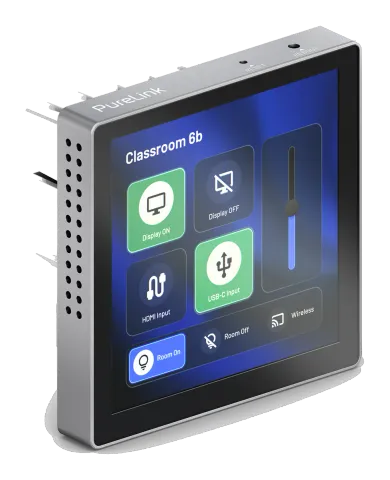
The PT-CON-TP40-SD is a programmable touch panel, designed to be utilized in the sectors of automated office system, multi-media room and smart home. With a programmable interactive user interface over configuration protocols, the integrated system provides intelligent networking service. The in-wall touch panel, with standard 86 box design, is equipped with a capacitive touch screen with a resolution of 480*480, and it supports one LAN port and one RS232 serial port. It is used in a diverse range of installations and applications across industries including multi-media conference rooms, multi-functional halls, training centers, show room, broadcasting studios and industrial automation.
Features
- ARM Cortex-A55 architecture 1.8Ghz main frequency.
- Android 11.0 system, 4GB DDR4 RAM, 32GB EMMC Flash.
- 4 inch 480*480 (1:1) resolution, capacitive touch screen, standard 86 box in-wall design.
- One machine with two modes, can be used as touch screen central control or user terminal.
- Support one RS232 serial communication port, which is capable of configuring 8 baud rates in the range of 2400-115200bps.
- Support access to the host system management web page with a password.
- Interface design and programming through Control DS design tools.
- Compliant with industry standard network communication protocols (TCP/IP, Http, UDP, Websocket).
- With 1 Gigabit network port, the highest rate up to 1G/bps.
- Dual power supply mode, supporting PoE or DC power supply.
- Support factory reset.
Panel Description
FRONT
- Touch Screen: Capacitive touch screen. The user control interface can be configured through the IDE tool.
TOP
- RESET button: Reboot: After the device boots up, press and hold the RESET button for more than 1s less than 5s, then release it, the device will reboot. The device won’t upload the user projects after rebooting. Reset: After the device boots up, press and hold the RESET button for more than 5s, then release it, the device will reset the user configuration information, the IP will be restored to the default settings (IP address: 192.168.0.101, subnet mask: 255.255.0.0), the login password of the management page will be initialized to “admin”, the device time will be initialized to automatic acquisition mode, but user projects won’t be deleted by factory initialization.
- REBOOT button: Used for screen off or wake-up.
Specifications
REAR
- USB port: Micro USB port. The reserved port for system debugging.
- LAN/PoE port: Standard 10M/100M/1000M Ethernet RJ45 port with default auto-negotiated speed for device connection, projects uploading & downloading, network communication and debugging. By default, the DHCP function of the control panel is disabled, and the IP setting is as follows: IP address: 192.168.0.101, subnet mask: 255.255.0.0
- POWER port: The power input port (2-PIN phoenix connectors), used for connecting with external 24V DC power supply.
- RS232 port: Programmable RS232 communication connector (male), compliant with RS232 protocol, and capable of configuring 8 baud rates in the range of 2400-115200bps. The pin-outs of the RS232 port are PIN1 for TX, PIN2 for GND, and PIN3 for RX.
| Technical | |
|---|---|
| CPU | ARM Cortex-A55 1.8GHz |
| Operation System | Android 11 |
| RAM | 4GB DDR4 RAM |
| Flash Memory | 32GB EMMC Flash |
| Resolution | 480*480 |
| Touch Type | Capacitive TouchScreen |
| ESD Protection | IEC 61000-4-2: ±8kV (Air-gap discharge) & ±4kV (Contact discharge) |
| Connection | 1x 3-pin Phoenix Connectors, for serial data communication |
| LAN/PoE | 1x Standard 10M/100M/1000M Ethernet RJ45 port, supporting PoE function |
| POWER | 1x 2-pin Phoenix Connectors, for power supply |
| DEBUG | 1x Micro USB, system debugging port |
| RS232 | RS232 serial port, which is a 3-pin Phoenix RS232 communication connector (male), compliant with RS232 protocol, and capable of configuring 8 baud rates in the range of 2400-115200bps. The pin-outs of the RS232 port are PIN1 for TX, PIN2 for GND, and PIN3 for RX. |
Mounting Instruction
This in-wall touch panel can be mounted on a standard 86 wall box, the mounting steps are as follows.
- Install the included wall mounting bracket onto the 86 wall box and fasten it with 2 screws.
- Align the back of the touch panel with the slots of the wall bracket and push it in. Press the aluminum edge of the touch panel to ensure that the buckles are in place, and the installation is complete.
Wall mounting bracket
86 wall box
44.5mm
To remove the mounted touch panel, insert a screwdriver into the two holes indicated by the arrows and pry the machine out of the bottom box.
General
| Housing | |
|---|---|
| Front Panel: | Touch Screen |
| Frame: | Plastic |
| Rear Case: | Plastic |
| Color | |
| Front Panel: | Black |
| Frame: | Black |
| Rear Case: | White |
| Dimensions (W x H x D) | 86 x 86 x |
| Net weight | 165g |
| Power supply | 24V DC/1A or PoE |
| Power consumption | 5W (Full Load) |
| Operating temperature | 0 to +40°C (32° to +104°F) |
| Storage temperature | -20 to +60°C (-4° to +140°F) |
| Operating Humidity | 20% to 80% (relative humidity, non-condensing) |
| Storage Humidity | 10% to 90% (relative humidity, non-condensing) |
Mounting Instruction
This in-wall touch panel can be mounted on a standard 86 wall box, the mounting steps are as follows.
- Install the included wall mounting bracket onto the 86 wall box and fasten it with 2 screws.
- Align the back of the touch panel with the slots of the wall bracket and push it in. Press the aluminum edge of the touch panel to ensure that the buckles are in place, and the installation is complete.
Wall mounting bracket
86 wall box
44.5mm
Touch Panel Operation Guide
Home Screen and Main Menu
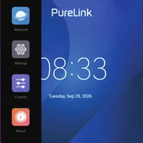
After the touch panel is powered on, the Home screen shown in Fig. 1 is displayed. Swipe from the left edge of the screen toward the right to open the main menu shown in Fig. 2.
Effect after installation
Touch panel 86 wall box
Fig. 1 — Home screen after power-on
The main menu provides access to the following functions:
- Network — Configure network information, including the touch panel IP address, subnet mask, gateway and DNS settings.
- Settings — Configure display brightness, date and time, language, operating mode and other system settings.
- Control — Open the control interface that has been designed and uploaded to the touch panel.
- About — View basic information about the touch panel.
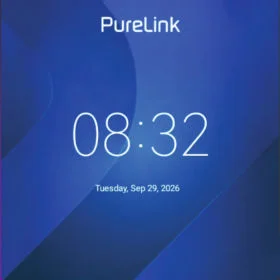
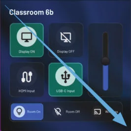
Fig. 2 — Main menu
Opening the Menu from the Control Interface
When the Control interface is displayed, swipe diagonally from the upper-left corner of the screen to the lower-right corner, as shown in Fig. 3. A right-pointing prompt appears at the left side of the screen. Tap this prompt to open the main menu.
Fig. 3 — Swipe gesture used to call up the menu from the Control interface
Operating Mode and Passwords
The touch panel operating mode can be changed under Settings > Operating Mode, as shown in Fig. 4. Before the operating mode can be changed, the system requests the Engineer Password. Enter Admin as the Engineer Password.
Fig. 4 — Operating Mode setting
When User mode is selected, a User Password must be defined. While the touch panel is operating in User mode, this User Password is required when opening Network settings and when exiting the Control interface, as shown in Fig. 5.
Fig. 5 — User Password prompt
Slave Mode
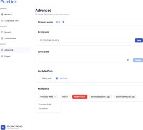
Open a web browser and enter IP/home using the IP address of the touch panel. On the Advanced page, open the mode selector under Maintenance and select Slave Mode, as shown in Fig. 6. In Slave Mode, the touch panel can operate as a terminal for accessing the control interfaces of other control devices.
Fig. 6 — Advanced page and Slave Mode selection
Firmware Upgrade
Accessing the Management Web Page
Using a web browser, enter IP/home to access the touch panel management web page. For example: 192.168.0.101/home. The default login password is admin.
At the first login, the system requires the default password to be changed. After logging in, open the Advanced page shown in Fig. 6.
Local Firmware Update
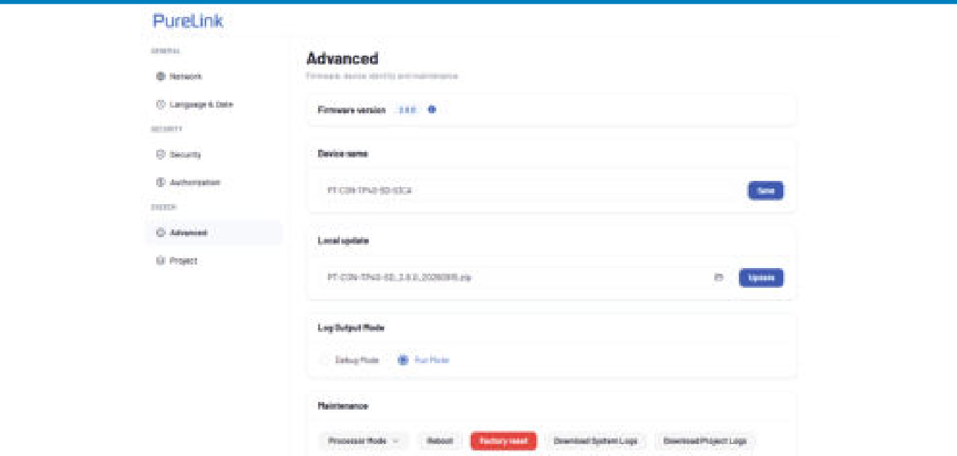
On the Advanced page, locate Local update as shown in Fig. 7. Select the supplied firmware upgrade package and click Update to upload the package. After the upload is completed, the system automatically restarts. Once the restart is complete, the firmware upgrade is finished. The installed firmware version can be checked either on the touch panel or on the management web page.
Fig. 7 — Local update with a firmware package selected
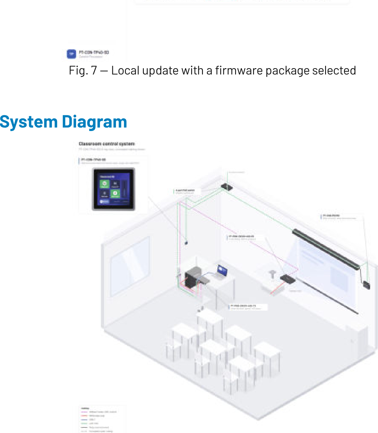
System Diagram
Conformity
PureLink GmbH hereby declares that this product is in compliance with the essential requirements and other relevant provisions of the Directive 2011/65/EU (RoHS), as amended, including Commission Delegated Directive (EU) 2015/863, and EMC Directive (2014/30/EU).
The EU Declaration of Conformity is available here:
www.purelink.com
Disposal of Device
WEEE-Reg.-Nr. DE 93847290
According to the European WEEE Directive, electrical and electronic equipment may not be disposed of with household waste. As a consumer, you are obliged to return electrical and electronic equipment free of charge at the end of its service life to the public collection points set up for this purpose or to the point of sale. Details on this are regulated by the respective national law.
The symbol on the product, the instructions for use or the packaging refers to these regulations. Recycling old appliances in this way is an important contribution to the protection of our environment.
Service, Warranty and Statutory Rights
If a fault or damage is detected, please contact your dealer or PureLink support. Please provide the product model, a detailed description of the fault and, where reasonably required, proof of purchase.
Any additional commercial warranty is subject to the applicable warranty terms. Statutory rights remain unaffected.
Liability
Use the product only as described in this manual. Improper installation, unauthorised modification, or use contrary to these instructions may cause damage and may affect warranty claims. Nothing in this manual excludes or limits liability where such exclusion or limitation is prohibited by applicable law.
Trademarks and Copyright
PureLink and the PureLink logo are trademarks of PureLink GmbH. All other trademarks mentioned in this manual are the property of their respective owners.
© 2026 PureLink GmbH. All rights reserved. No part of this manual may be reproduced without the prior written permission of PureLink GmbH, except where permitted by applicable law.
For further support or questions please contact us under
www.purelink.com
or scan the QR-code below

Legal & Compliance
Product identification
Model: PT-CON-TP40-SD – manual version 1.0
Packaging
Dispose of packaging separately by material (paper/cardboard, plastics) via the local collection systems. Keep packaging material away from children – risk of suffocation. Packaging register LUCID: DE5958616449295.