
Safety precautions
- Unpack the equipment carefully and save the original box and packing material for possible future shipment.
- Follow basic safety precautions to reduce the risk of fire, electrical shock and injury to persons.
- Do not dismantle the housing or modify the module. It may result in electrical shock or burn.
- Using supplies or parts not meeting the products’ specifications may cause damage, deterioration or malfunction.
- Refer all servicing to qualified service personnel.
- To prevent fire or shock hazard, do not expose the unit to rain, moisture or install this product near water.
- Do not put any heavy items on the extension cable in case of extrusion.
- Do not remove the housing of the device as opening or removing housing may expose you to dangerous voltage or other hazards.
- Install the device in a place with fine ventilation to avoid damage caused by overheat.
- Keep the module away from liquids.
- Spillage into the housing may result in fire, electrical shock, or equipment damage. If an object or liquid falls or spills on to the housing, unplug the module immediately.
- Do not twist or pull by force ends of the optical cable. It can cause malfunction.
- Do not use liquid or aerosol cleaners to clean this unit. Always unplug the power to the device before cleaning.
- Unplug the power cord when left unused for a long period of time.
- Information on disposal for scrapped devices: do not burn or mix with general household waste, please treat them as normal electrical wastes.
Product Introduction
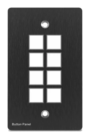
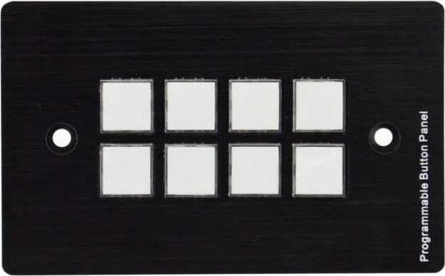
The programmable control panel is a Wall Control Panel. Every button is programmable and works either individually or together. The programmable control panel is built in the programmable 3 RS232, 1 RS485, 3 Infrared & 2 Relay, and 1 mini USB for programming.
Please notice, RS232 (1) and IR2 share the same port, cannot be used at the same time. Also, RS232 (2) and IR3 share the same port, cannot be used at the same time.
It can fully control our product, as well as third party devices such as projectors, screens etc. It is an easy-to-use control device for presentation show rooms, classrooms and boardrooms.
Features
- Every button can be programmed to send the bi-direction RS232 and RS485 commands simultaneously to control third party devices.
- Every button can be programmed to send the infrared code, control the relay, to let them work simultaneously to control the third party devices.
- Every button is built in the infrared code and RS232 code learning function, and baud-rate setting.
- ID looping function. 99pcs programmable control panels can be looped and controlled together, by ID identifying.
- Programmed by USB or RS232, working with the PC software (PS-WP).
- Crystal and backlit buttons with easy user-friendly customizable changeable labels.
- The backlit brightness is controllable.
- Dimension: 11.4cm long and 7cm wide.
Package List
- 1 x Programmable Control Panel
- 1 x Power Adapter (12V DC)
- 3 x 2-pin Captive Screw Connector
- 2 x IR Emitter
- 8 x Button Caps
- 1 x Button Label
- 1 x USB Converting Cable
- 1 x User Manual
Note: Please contact your distributor immediately if any damage or defect in the components is found.
Installation
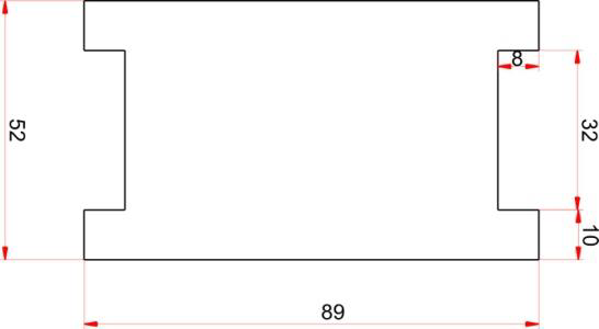
- Firstly, dig a hole on the desk to the size marked on the aperture paper (shown in Figure 1-1).
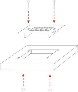
- Secondly, put the device into the hole and adjust it to flush with the table (shown in Figure 1-2).
- Then, plug a set screw into the fixing mounting and screw the nuts tightly.
Figure 1- 1 Aperture paper
Figure 1- 2 Installation Guide
Front Panel
Crystal and luminescent, programmable buttons:
Every button can be programmable with the software PS-WP.
Connect the PC via USB or RS232.
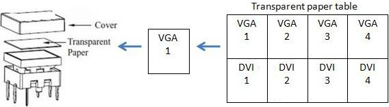
And every label inside the button can be changeable. You can choose the label you need and change it very easily like below:
(For the specific transparent paper table, please contact the local distributor or reseller for it)
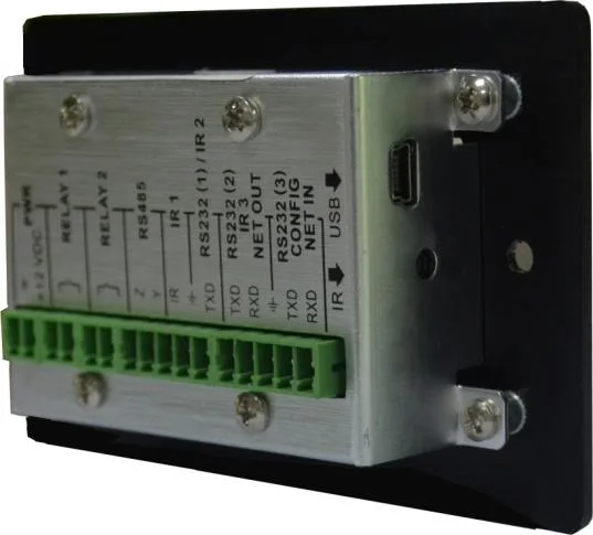
Side Panel
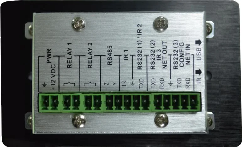
Rear Panel
The programmable control panel has various ports in the rear panel, including Lopping port, RS232 port, RS485 port, IR port, Relay port and Power port. Below is the introduction:
Note: When use this USB port to program the control panel’s buttons, the available COM port number should not be more than 10.
Mini USB Connector:
1. Communicate with PC which uses PS-WP to program the buttons.
2. Transmit the infrared data when learning IR (Optional).
Infrared sensor port:
receive and learn the IR code, to build the IR database.
① Power connector: 12VDC. Be sure that the “+” and “-” never be mixed or wrong connection.
② Low-Voltage relay ports: set the relay on/off by software PS-WP.
③ This port includes: RS232 (1)/IR2, IR1 and RS485.
• RS232 (1)/IR2: share the same port, the detailed use depends on the setting of PS-WP. When be used as RS232, it is unidirectional transmission, transmit data but without receive.
• IR1: for control other devices, it can be programmable by the PS-WP.
• RS485: the RS485 can be programmed as different commands and control the device with RS485 port. The command of RS485 is the same as RS232 (1).
④ This port includes two parts:
• One part is RS232 (2)/IR3, it can be used for control other devices or looping output. RS232 (2) and IR3 share the same port, the detailed use depends on the setting of PS-WP.
• Other part is RS232 (3), it can be used for control other devices or looping output, or connect with PC.
These two parts share the same grounding.
System Diagram
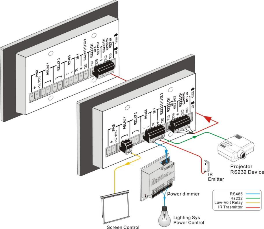
The programmable control panel can active different ports at one time. It means every button can send the RS232 and RS485 commands, IR code and control the relay at the same time. The demo system diagram as below:
Connection of Programming and Looping
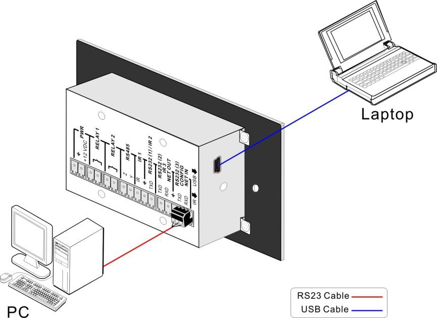
The programmable control panel can be connected to the computer for programming, to default the functions of every button. It can be connected by USB or RS232, working with the PS-WP software. It is shown as below:
Programming Connection
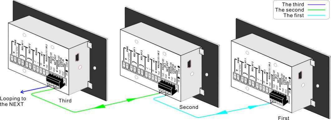
Several pieces programmable control panels can be also looped to be a system, for control more devices. It is looped by the inter RS232 setting. Please check the demo picture as below:
Several programmable control panels Looping connecting
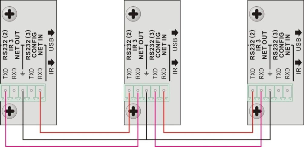
After connect the programmable control panels as above, and then we should set the ID of each programmable control panel by PS-WP. The ID number is from 01 to 99, and it also is the class of the programmable control panel in the loop, different programmable control panels should set to different ID. After connections finish, we can set the control modes by PS-WP. For detailed connecting, please check the picture below:
Detailed looping connecting
Note: Up to 99 programmable control panels can be looped within one system. However, to achieve normal interaction, loop less programmable control panels (10 tops) in the system.
Second classLast class …
USB Driver Installation
There are USB driver file and PS-WP software in the disk. The PS-WP can run directly without installation. But when connect the programmable control panel with PC by USB, it may need to install the USB driver. Use the driver file to install the driver of USB, we can use USB to program the programmable control panel.
Software Programming
You can use this software PS-WP to easily set every button of the programmable control panel.
After connect the programmable control panel with PC by USB or RS232, we can open the PS-WP to program the buttons for controlling.
The main window of PS-WP has five parts: main menu, panel (button) setting, event setting, action list and event list. In this manual we will take programmable control panels-V for example, to show the uses of all functions.
The main window of PS-WP is as below:
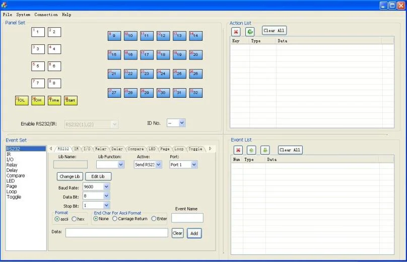
We will introduce all the configurations one by one.
Main Menu
The main menu includes file management, system model, connection type and help.
- File management: Open/Save/Save as a configuration. After program, user can save the configuration to a file, so that you can use the same configuration next time.
- System model: includes programmable control panels-H, programmable control panels-V, WP19R etc, and the buttons interface view are different with different models. The pictures below show the differences between programmable control panels-V and programmable control panels-H.
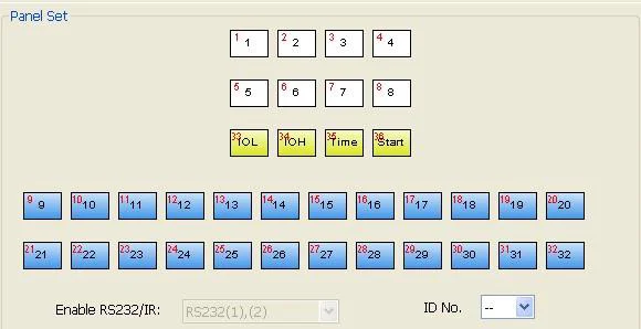
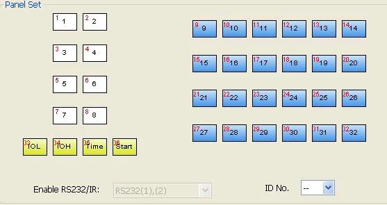
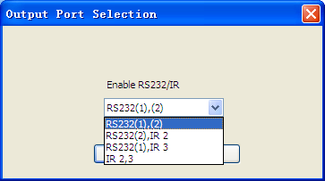
Note: When select the model, it will pop up “Output Port Selection” dialog, user can select different RS and IR types, depend on the uses of the two shared ports. The dialog is as the picture below:
| Output port of the Panel | Output mode of PS-WP | IR1 | RS232(1) | IR2 | RS232(2) |
|---|---|---|---|---|---|
| RS232(1)(2) | √ | √ | √ | √ | √ |
| RS232(2),IR2 | √ | √ | √ | √ | |
| RS232(1),IR3 | √ | √ | √ | √ | √ |
| IR2,3 | √ | √ | √ | √ | |
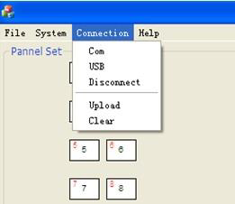
- Connection type: the instructions are in the picture below:
The functions of the programmable control panel’s buttons will be available only after
1:Com, connect by serial port.
2:USB, connect by mini USB.
3:Disconnect, disconnect the connection.
4:Upload: upload the programmed data to the programmable control panel. It will clear all the old data in the programmable control panel.
5:Clear, clear the data in the programmable control panel.
the programmed data is uploading successfully.
- Help: Show the information of PS-WP.
Panel/Key setting
There are three different colors of keys in the panel set of PS-WP. Add a key action to action list, then add events to this action, make this action will execute the events.
Here take programmable control panels-V for example, to introduce the uses of different buttons:
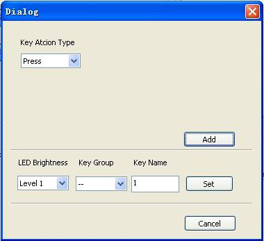
- White keys: keys 1-8, correspond to the buttons on the programmable control panel. Click the key, it will pop up dialog as below:
When select the type “Toggle”, the setting interface is as below:
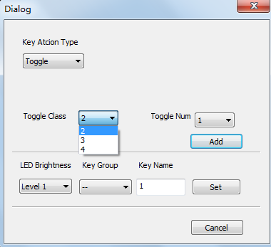
The toggle class is the action loop class, depends on the numbers of looped actions. When the class is 2, there are two actions in the toggle. And so on.
- Key Action Type:
- Press: Execute events when press button.
- Release: Execute events when release button.
- Page: Built-in most 4 actions, actions need to be switched by other buttons, press to execute.
- Toggle: Built-in most 4 actions, actions will loop run when press. Actions can also be switched by other buttons, press to execute.
- Blue Keys: Keys 9-32, all are virtual keys, used in the loop function. When use the loop function, the ID must be set, the ID can be 1 to 99. Press “add” will add the button to action list.
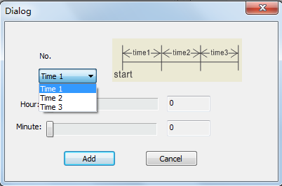
- Yellow Keys: Keys 33-36, all are virtual keys. Key 33 and 34 are for I/O control, which is not supported with the programmable control panel. Key 36 is a start action, if add events to this action, when the programmable control panel is power on, it will execute the events in this action. Key 35 is delay button, there are three time slots can be set. See in the picture below:
The time is counted from the programmable control panel start. When come to time1, the programmable control panel will execute the events in time1. Then recount from time2, and then time3.
Example: Set time1 to 5 minutes, and time2 to 3 minutes, add event1 to time1 and event2 to time2. When the unit starts, it will execute event1 after 5 minutes, and then execute event2 after 8 minutes.
Action list
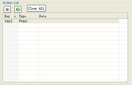
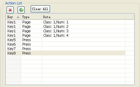
Action list shows all the set actions. An available action must be added to the list. The action list is as the picture below:
Event setting
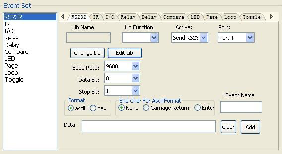
Event setting includes RS232, IR, I/O, Relay, Delay, Compare, LED, Page, Loop and Toggle setting. Before set events, an action must be added first. The following introduction will show you the setting of each event:
RS232 Setting
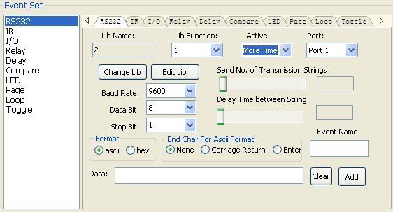
This item is used for setting the parameters of the programmable control panel’s serial ports. Click “RS232”, it will show as below:
- Send
- Type
- Send
- Port
- Delete a selected action.
- Refresh, delete all the actions that with no event.
- Delete all actions.
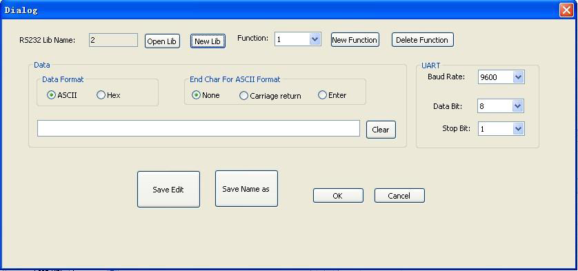
- The data of RS232 can be directly entered or selected from library. Click “Change Lib” to select a library file and open it. Click “Edit Lib” to create or edit a library file as below:
Note: When editing finish, remember to save the editing, and then press “OK”.
- There are two send types: send once and send more times. When select “more times”, the send times and the delay between times can be set. See in picture below:
- The send port must be selected as the same as model setting, otherwise the event cannot be added.
- Enter the serial command for device control.
- Create/delete the function name of the command
- Create/open a library
- User can set the event name. It is optional function, not necessary.
IR Setting
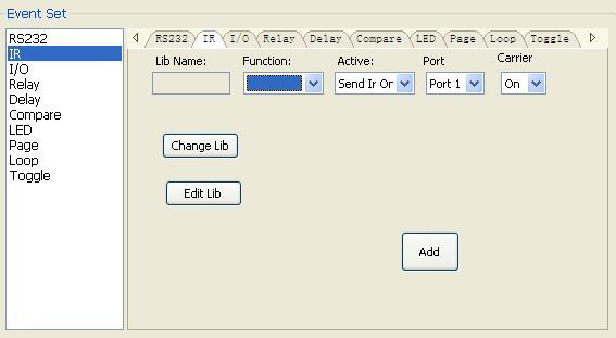
This item is used for setting the parameters of the programmable control panel’s IR ports. Click “IR”, it will show as below:
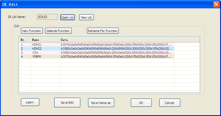
- The data of IR need to be selected from library. Click “Change Lib” to select a library file and open it. Click “Edit Lib” to create or edit a library file as below:
Select a function, and then click “learn”, press the IR remote button to send the IR code to infrared sensor port, it will refresh the IR data. Follow the same steps can learn any function of the remote buttons.
- Create/delete/rename the function name of the IR data
- Create/open a library
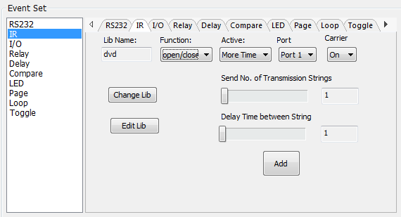
- There are two send types: send once and send more times. When select “more times”, the send times and the delay between times can be set. See in picture below:
- The send port must be selected as the same as model setting, otherwise the event cannot be added.
- The IR can set the carrier on/off, to turn on/turn off the IR sending.
I/O Setting
Note: There is no I/O port in the programmable control panel, so the setting is not introduced in this manual.
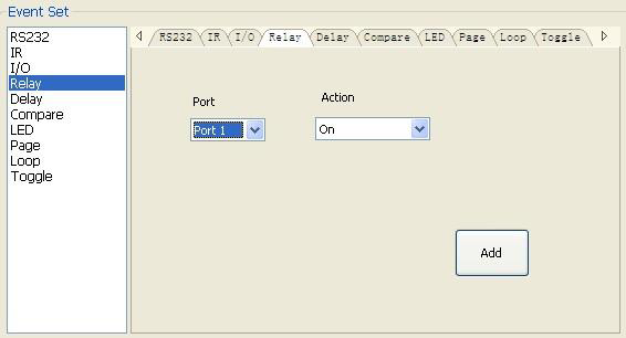
Relay Setting
This item is for the replay ports setting. The setting is as the picture below:
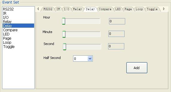
Delay setting
This item is to set a delay time, user can add a delay between two events; so when one event is finished, it will delay a certain time then start another event. The delay setting is as picture below:
Compare Setting
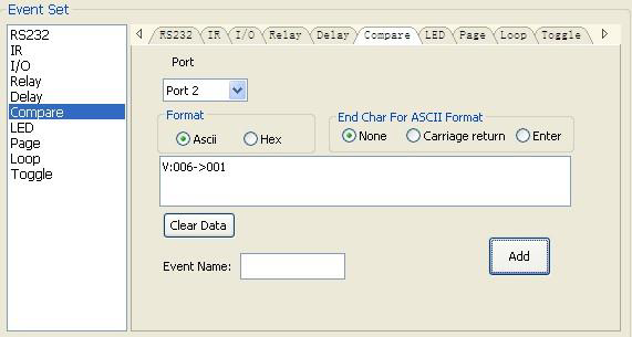
This item is used for compare the feedback of RS232 commands. When the programmable control panel send a RS232 command to the controlled device, the device will send back a feedback. If we add the correct feedback in the data, the programmable control panel will compare it with the feedback received from controlled device, to verify the command is work or not. The compare setting is as the picture below:
1) The send port must be selected as the same as model setting, otherwise the event cannot be added. And port 1 cannot be used for compare, for there is no a receive pin in this port.
2) User can set the event name; it is optional function, not necessary.
3) For the events in one event list have priority, from top to bottom, so that the compare function can be used in action which with three or more events. When send a serial command, we can add a compare then other events. If the compare is incorrect, the event behind compare will not be executed.
Enter the compare commands, don’t miss any character.
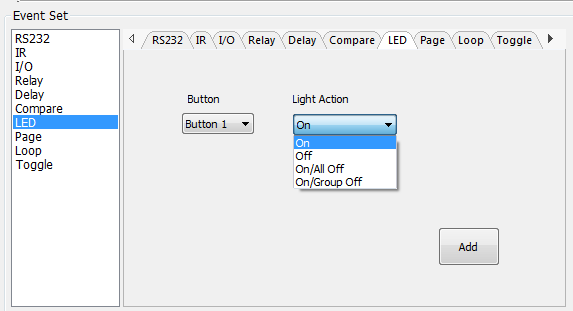
LED setting
This item is used for set the button LEDs in the programmable control panel to turn on/off. The setting is as below:
Page setting
White buttons can be set to type “page” that include four actions. To change different actions, it will need other white buttons to active the page action number. Here take an example to show you the use of this function:
1) Take button1 for example: click key1 and select the action type “page”, add the four actions to the action list. Then add other four buttons “press” action to the list (here take keys 5-8 for example):
2) In event setting, we add four different events to the four page actions of key1, and the four other keys will be added the page event to each of them as below:
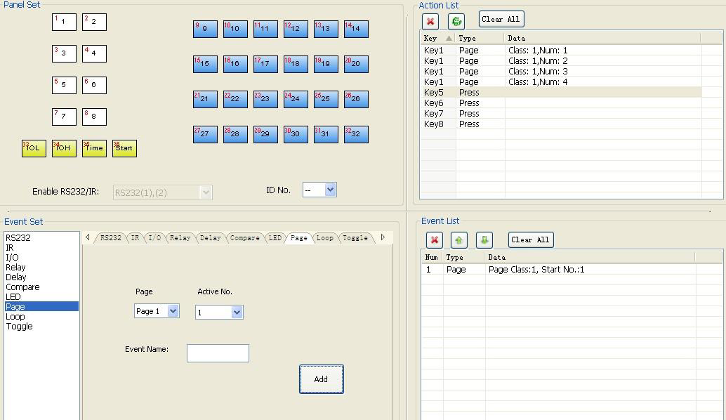
Then set the “page” event to make four “press” actions to active the four page number: key5-num1, key6-num2, key7-num3 and key8-num4. It will perform like this:
- When press the button5 and then button1, the button1 will execute the event of num1, press button1 more times it will execute num1 more times;
- When press the button6 and then button1, the button1 will execute the event of num2, press button1 more times it will execute num2 more times;
- When press the button7 and then button1, the button1 will execute the event of num3, press button1 more times it will execute num3 more times;
- When press the button8 and then button1, the button1 will execute the event of num4, press button1 more times it will execute num4 more times.
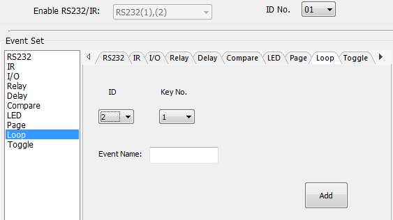
Loop Setting
This item is used for looping the programmable control panel. When use the loop function, the ID of each programmable control panel must be set.
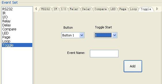
Toggle Setting
The toggle setting is as the picture below:
Event List
The setting steps of toggle are similar with the page setting. But toggle performs differently, for the actions in it are loop running, it will perform as below (take the same example like page function):
- When press the button5 and then button1, the button1 will execute the event of num1, press button1 more times it will execute num2, then num3→num4→num1 and so on.
- When press the button6 and then button1, the button1 will execute the event of num2, press button1 more times it will execute num3, then num4→num1→num2 and so on.
- When press the button7 and then button1, the button1 will execute the event of num3, press button1 more times it will execute num4, then num1→num2→num3 and so on.
- When press the button8 and then button1, the button1 will execute the event of num4, press button1 more times it will execute num1, then num2→num3→num4 and so on.
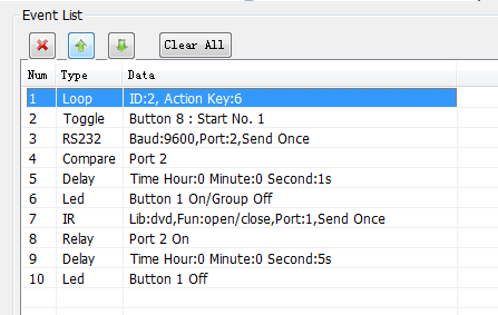
The event list shows all events of the selected action. The executing priority abides by the serial number, see the picture below. If there is an event execute incorrectly, all the events behind it will not be executed.
Specification
| Parameter | Specification |
|---|---|
| Program Port | USB or RS232 |
| Output Port | (3) RS232, (1) RS485, (3) IR, (2) Relay |
| Serial Control Port | RS232 |
| Baud Rate And Protocol | 9600 baud, 8 data bits, 1 stop bit, no parity |
| Software | PS-WP |
| Frequency Response | 20Hz ~20KHz |
| Operation Temperature | -10 ~ +55℃ |
| Storage Temperature | -25 ~ +70℃ |
| Relative Humility | 10%-90% |
| Power Supply | Input: 100VAC~240VAC, 50/60 Hz; Output: 12V DC 2A |
| Max Power Consumption | 1W |
| Dimension (W*H*D) | 114mm x 70mm x 28mm |
| Net Weight | 150g |
Panel Drawing
+12 VDC
PWR
RS232 3( )
NET IN
RS485
RS232 2( )
NET OUT
CONFIG
IR USB
IR 3
RS232 1( ) / IR 2
IR 1
RELAY 1
RELAY 2
114 mm
70 mm
28 mm
25 mm
Troubleshooting & Maintenance
- When the control panel cannot work, please check and make sure the power cord connection is well, plug cannot be mixed or connect wrong. Then restart, if still not work, the control panel may be broken. Please send it to the dealer for repairing.
- When USB cannot open or without response, please make sure the USB driver is installed correctly, and then reconnect the USB cable.
- When uploading the USB cannot be found, please restart the software or panel.
- When the LED of a button cannot be lighted, please check if there is a compare event in this button. If yes, delete the compare and try again. If still not work, the LED may be broken. Please send the unit to dealer for repairing.
- When serial commands sending without function executed, please check the baud rate and make sure is correct, and the serial connection is well.
- If the controlling queue is confused when use loop function, please reboot the programmable control panel.
Customer Service
The return of a product to our Customer Service implies the full agreement of the terms and conditions hereinafter. There terms and conditions may be changed without prior notice.
- Warranty The limited warranty period of the product is fixed three years.
- Scope These terms and conditions of Customer Service apply to the customer service provided for the products or any other items sold by authorized distributor only.
- Warranty Exclusions:
- • Warranty expiration.
- • Factory applied serial number has been altered or removed from the product.
- • Damage, deterioration or malfunction caused by:
- Normal wear and tear.
- Use of supplies or parts not meeting our specifications.
- No certificate or invoice as the proof of warranty.
- The product model showed on the warranty card does not match with the model of the product for repairing or had been altered.
- Damage caused by force majeure.
- Servicing not authorized by distributor.
- Any other causes which does not relate to a product defect.
- • Shipping fees, installation or labor charges for installation or setup of the product.
- Documentation: Customer Service will accept defective product(s) in the scope of warranty coverage at the sole condition that the defeat has been clearly defined, and upon reception of the documents or copy of invoice, indicating the date of purchase, the type of product, the serial number, and the name of distributor.
Remarks: For further assistance or solutions, please contact your local distributor.
Legal & Compliance
Product identification
Model: PT-CON-WP8B – manual version 1.0
Trademarks and disclaimer
Product model and logo are trademarks. All other company and product names mentioned are trademarks of their respective owners. All rights reserved. No part of this publication may be copied or reproduced without prior written permission. We reserve the right to make changes to the device, packaging or manual and accept no liability for misprints.
FCC
FCC FCC FCC FCC Statement It has been tested and found to comply with the limits for a Class B digital device, pursuant to part 15 of the FCC Rules.
Disposal of electrical and electronic equipment
WEEE reg. no.: DE 93847290
The crossed-out wheelie bin symbol on the product, packaging or in this manual means that electrical and electronic equipment must not be disposed of with household waste at the end of its life. Hand in old devices free of charge at a public collection point or return them to a distributor obliged to take them back. Remove batteries and lamps that can be removed without destroying the device before handing it in, and delete any personal data stored on the device. Details are regulated by national law. By returning old devices you help protect the environment.
Packaging
Dispose of packaging separately by material (paper/cardboard, plastics) via the local collection systems. Keep packaging material away from children – risk of suffocation. Packaging register LUCID: DE5958616449295.