
Safety and Notice
Please read all of these instructions carefully before you use the device. Save this manual for future reference.
The PT-E-HD50 HDMI Extender over Single Cat.X with HDBaseT, RS232, Bi-directional IR, Ethernet & POC has been tested for conformance to safety regulations and requirements, and has been certified for international use.
However, like all electronic equipments, the PT-E-HD50 should be used with care. Please read and follow the safety instructions to protect yourself from possible injury and to minimize the risk of damage to the unit.
- Follow all instructions and warnings marked on this unit.
- Do not attempt to service this unit yourself, except where explained in this manual.
- Provide proper ventilation and air circulation and do not use near water.
- Keep objects that might damage the device and assure that the placement of this unit is on a stable surface.
- Use only the power adapter and power cords and connection cables designed for this unit.
- Do not use liquid or aerosol cleaners to clean this unit. Always unplug the power to the device before cleaning.
Introduction
The PT-E-HD50 HDMI Extender over Single Cat.X with HDBaseT, RS232, Bi-directional IR, Ethernet & POC boosts up your video/audio transmission distance up to 100m (330ft) in HDTV 1080p with 48-bit color depth. PT-E-HD50 also supports the most advanced 3D video format complaint with HDMI specification and therefore guarantees the highest 3D video compatibility on the market. With only one cost effective Cat.5/5e/6 cable, users can readily extend HDTV sources from DVD players, Blu-ray Disc player, PS3, PC, and any other kinds of sources compliant with TMDS to distant display monitors including HDMI or DVI enabled TV sets or LCD PC monitors. With the advanced design for the latest HDMI technology, deep color video, DTS-HD or Dolby TrueHD audio, and HDCP supports and compatibility are all further insured. This flexibility makes HDCP compliant DVD players or PS3 transmit utmost high quality video and audio with a greater distance at the minimal cost, when integrating several components apart.
In addition, PT-E-HD50 is also equipped with bi-directional IR pass-through path and RS-232 serial port control. These bonus features allow users to boost IR control distance up to 100m (330ft) and make IR control possible through only single Cat.5/5e/6 cable including HDMI signals. In addition, serial port offers the convenient path for interactive application, such as touch panels. In addition, PT-E-HD50 also supports POC (Power over Cable) which can power both units from TX or RX with power supply.
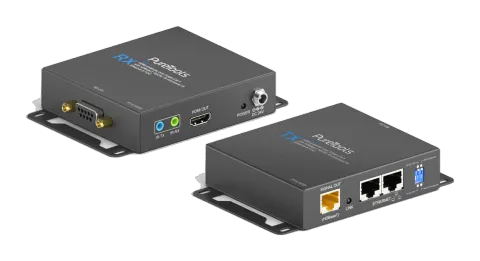
The PT-E-HD50 includes two units: transmitting unit PT-E-HD50-TX and receiving unit PT-E-HD50-RX. The transmitting unit is used to capture the input HDMI / DVI signals with IR control packets. The receiving unit is responsible for equalizing the transmitted HDMI signal and reconstructing IR and serial control signals. PT-E-HD50 offers the most convenient solution for digital signage with long distance A/V transmission path, and with 10G transmission bandwidth ready, PT-E-HD50 is ready for your next HDMI generation and applications!
- Supports HDMI Deep Color, full 3D & 4K2K@30 (HDBaseT technology)
- Extends the transmission up to 100m (330ft) from the HDMI source at Full HD 1080p 48-bit and 80m (264ft) at 4K2K@30
- Supports POC(Power over Cable) which can power both units from TX or RX with power supply.
- HDCP & EDID Bypass
- CEC support
- Auto equalization
- Pure unaltered uncompressed 7.1ch digital HDMI over Cat.5/5e/6 cable transmission
- DTS-HD Master Audio and Dolby TrueHD high bit rate audio support
- Supports full frequency IR signal from 20KHz to 60KHz
- Bi-directional IR path-through
- Full Duplex RS-232 control up to 115,200 bps through connector
- Integrated port for LAN/ network device
- Wall mounting housing design for easy and robust installation
Package Contents
Before you start the installation of the switch, please check the package contents.
- PT-E-HD50 [TX & RX] x1
- IR blaster x1
- IR receiver x1
- DC 24V x2
- User’s Guide x1
Panel Descriptions
FRONT PANEL — PT-E-HD50, transmitting unit (TX)

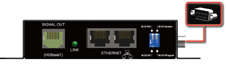
- RJ45: Plug in a Cat-5/5e/6 cable that needs to be linked to the transmitting unit RX.
- LED: TX /RX link indicator
- Ethernet port for LAN: Connect to network device
- DIP Switch:
- PIN#1: Setup the RS-232 mode for serial communication channel.
- PIN#2: For Firmware Update
- RS-232: Connect to serial port device with a DSUB-9 male-male or male-female cable here F/W update for Valens.
REAR PANEL — PT-E-HD50, transmitting unit (TX)
- IR Blaster: Infrared 3.5mm socket for plugging in the extension cable of IR blaster
- IR Receiver: Infrared 3.5mm socket for plugging in the extension cable of IR receiver
- HDMI IN: Connects to a HDMI source with a HDMI male-male cable
- Mini-USB: F/W update
- LED: Power indicator
- +24V DC: Connect to a 24V DC power supply.
FRONT PANEL — PT-E-HD50, receiving unit (RX)
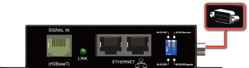
- RJ45: Plug in a Cat-5/5e/6 cable that needs to be linked to the transmitting unit TX.
- LED: TX /RX link indicator
- Ethernet port for LAN: Connect to network device
- DIP Switch:
- PIN#1: Setup the RS-232 mode for serial communication channel.
- PIN#2: For Firmware Update
- RS-232: Connect to serial port device with a DSUB-9 male-male or male-female cable here F/W update for Valens.
REAR PANEL — PT-E-HD50, receiving unit (RX)
- IR Blaster: Infrared 3.5mm socket for plugging in the extension cable of IR blaster
- IR Receiver: Infrared 3.5mm socket for plugging in the extension cable of IR receiver
- HDMI OUT: Connects to a HDMI display with a HDMI male-male cable
- LED: Power indicator
- +24V DC: Connect to a 24V DC power supply.
DIP Switch Position
| DIP Switch Position | Description |
|---|---|
| TX & RX PIN#1 ON [⬇] | TxD: The 2nd pin of RS-232, which is in charge of sending data RxD: The 3rd pin of RS-232, which is in charge of receiving data |
| TX & RX PIN#1 OFF [⬆] | TxD: The 3rd pin of RS-232, which is in charge of sending data RxD: The 2nd pin of RS-232, which is in charge of receiving data |
| PIN#2 ON [⬇] | Firmware Update |
| PIN#2 OFF [⬆] | Normal |
IR Pass-through
IR Extenders
- IR Blaster
- IR Receiver
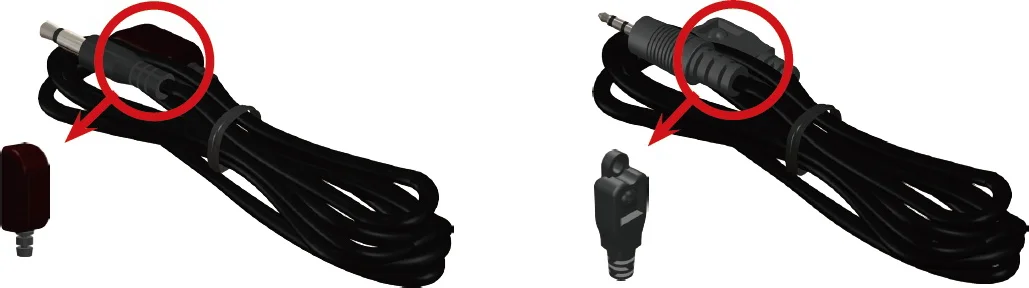
IR Sockets
IR BLASTER: plug in the IR blaster to emit all IR command signals received from the IR receiver from the other end to control the devices corresponding to the IR signals.
IR RECEIVER: plug in the IR receiver to receive all IR command signals from the IR remote controls of the corresponding devices.
Caution: Incorrect placement of IR Blaster and Receiver may result in the failure of the IR extenders. Please check carefully before plugging in the IR extender to the respective IR sockets. Warranty will not cover the damage.
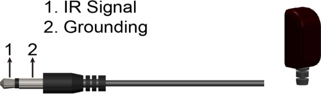
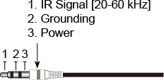
Definition of IR Earphone Jack
- IR Blaster
- IR Receiver
You can buy any IR extension cables in the market that are compatible to the definition of the IR sockets for the matrix if necessary for replacement use. However, IR cables longer than 2m (6-ft) may not work.
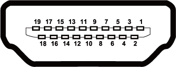
HDMI pin Definition
Type A (Receptacle) HDMI
| Pin 1 | TMDS Data2+ |
|---|---|
| Pin 2 | TMDS Data2 Shield |
| Pin 3 | TMDS Data2– |
| Pin 4 | TMDS Data1+ |
| Pin 5 | TMDS Data1 Shield |
| Pin 6 | TMDS Data1– |
| Pin 7 | TMDS Data0+ |
| Pin 8 | TMDS Data0 Shield |
| Pin 9 | TMDS Data0– |
| Pin 10 | TMDS Clock+ |
| Pin 11 | TMDS Clock Shield |
| Pin 12 | TMDS Clock– |
| Pin 13 | NC |
| Pin 14 | Reserved (N.C. on device) |
| Pin 15 | SCL |
| Pin 16 | SDA |
| Pin 17 | DDC/CEC Ground |
| Pin 18 | +5V Power |
| Pin 19 | Hot Plug Detect |
Installation
- Connect a HDMI or DVI source (such as a Blu-ray Disc player) to the transmitting unit PT-E-HD50-TX.
- Connect a HDMI or DVI display (such as a LCD TV) to the receiving unit PT-E-HD50-RX.
- Connect IR Blaster/Receiver to both TX and RX units.
- Connect USB cable to PC/Laptop
- Connect a Cat-5/5e/6 cable between the transmitting and receiving units.
- Make sure this Cat-5/5e/6 cable is tightly connected and not loose.
- Plug in 24V DC power supply unit to the power jack of the transmitting unit PT-E-HD50-TX.
Introduce
What is HDBaseT Manager?
HDBaseT Manager is the specialized software focusing on detecting the connecting environment and providing in-time investigation on the device that equipped Valens chip inside to find the potential problems in house efficiently and easily.
How does HDBaseT Manager help?
HDBaseT Manager offers the service in 4 parts
- Firmware : Enable the viewer to quickly understand the firmware version and update the firmware.
- Status : Easily to know the status and environment of connection condition.
- Burn-In Test : Allow the engineer or installer to get a technical file that reveal the unusual situation for analyze accurately.
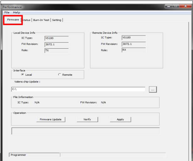
Firmware
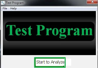
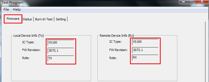
Check the current firmware version.
The upper part reveals the IC type/firmware version on the TX and RX.
Update the required firmware
In the lower parts, we will see the information as below
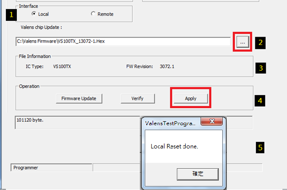
Whenever want to update the firmware, follow the steps as below :
- Select Local(TX) or Remote(RX) for firmware Update.
- Select the firmware file from your PC
- Review the file information of the selected firmware.
- Select to get firmware updated and verified at the same time
Status (Connecting)
Note: the setting will affect the status page and Brun-in Test function work.
Push in the corner to get all the information of connecting.
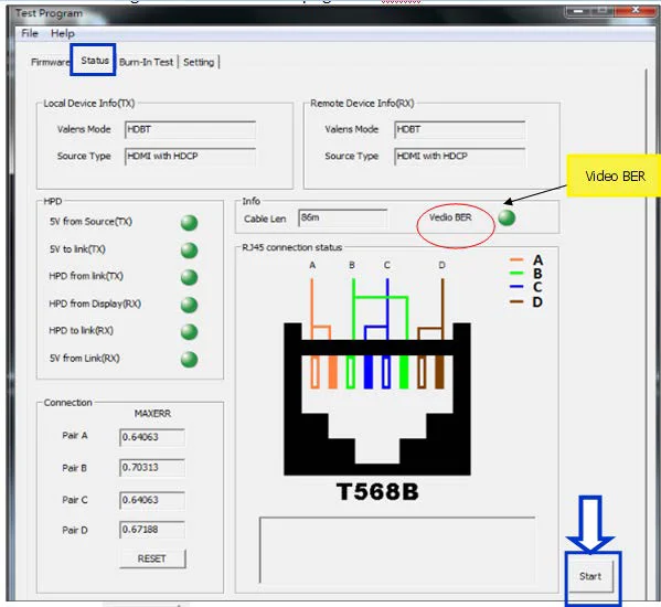
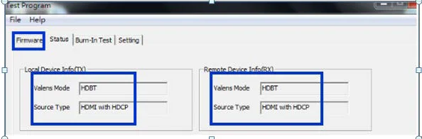
Check the status of connecting
- In upper part, it will reveal the Valens Mode and Source type.
- If Connected successfully, you will see the shown as below : - Normal
- If fail to connect, you will get the status as below :
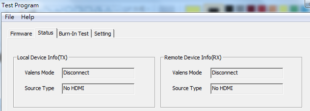
Indication radio the light to recognize the connection condition
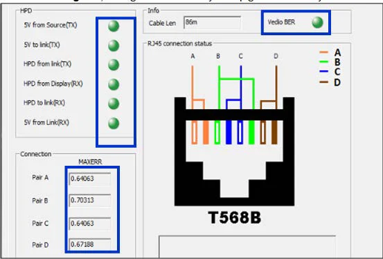
To review the Status of connecting, HDBaseT Manager analyze in 4 directoins
| Item | What is this for? |
|---|---|
| HPD | Hot Plug Detect when you plug in or unplug, re-initializing the HDMI link if necessary |
| Cable len | To measure the cable length |
| Video BER | The Bit Error divided of transferred bits during a studied time interval (video bit error rate) |
| MAXERR | MAXERR is used to denotes the largest error between the samples of the original signal and the reconstructed signal |
If the status is good, the light should always keep green without yellow or red.
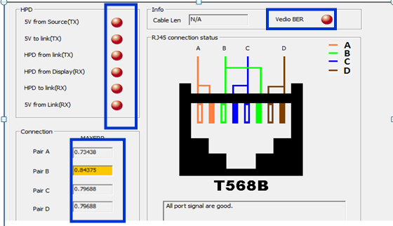
If the status is poor, the light will turn to yellow or red.
Burn-In Test
Get the technical file to analyze the unusual situation
If the connection is fine, the lines will stay straight all the time.
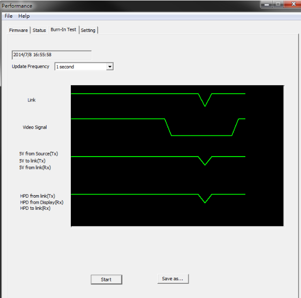
If there’s error detected, you will drops as shown below.
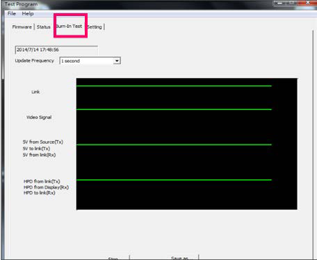
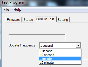
Select the required polling period and push to get the data.
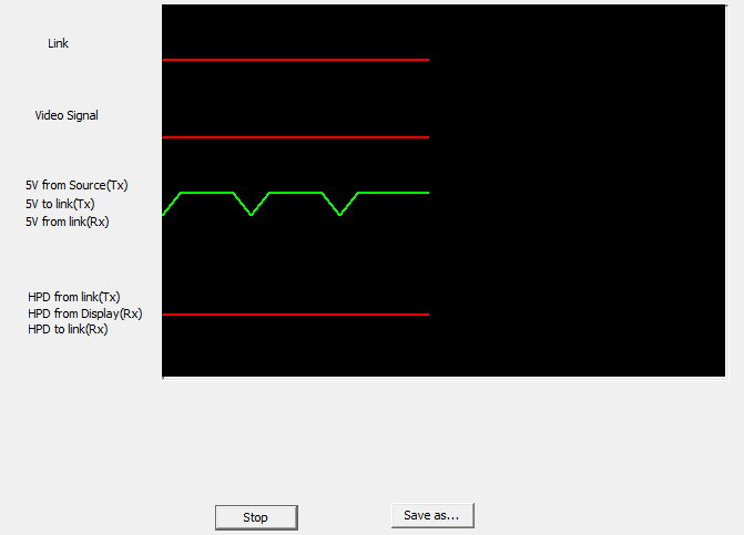
Select and send the file to the engineer for analyzing.
Fail-Safe Setting
Setting & saving the setting into on board MCU to ensure the stability during transmission.
- Through this manual setting, the device will be able to re-set once the selected conditions are fulfilled at the same time, this will ensure the quality and stability when signals transmission.
- Sensitivity for fail-safe mechanism.
- quality in wire, please choice 48, vice versa
- Select the STD for video error, according to HDMI association, the tolerance of Bit Error in transmit should be less than 10 -9 ,we use -9 to stand for this, so if you are in high tolerance in signals transmit error, please choice -8 for standard.
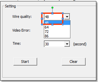
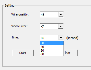
- Select the time interval, actually, our device will detect the factors every 0.5 second, if the above trouble (wire quality/ video error) last as long as the set time interval, the device will reset automatically to ensure the good quality in signal transmit. When you choice 30s, that means once the trouble (wire quality/ video error) last for 30s(non-stop), the machine will re-set immediately, that is, if you are in higher tolerance in the time interval of trouble, you can select 40 second or above.
The combination we suggest for standard usage is as below:
- Wire Quality: 64
- Video Error: -8
- Time: 30 seconds
Push to finish the setting.
Section 3: Specifications
| Item | Description |
|---|---|
| Units | Transmitting unit of PT-E-HD50 Receiving unit of PT-E-HD50 |
| Unit Description | Transmitter / Receiver |
| HDMI compliance | HDMI Deep Color, full 3D & 4K2K@30/40m |
| HDCP compliance | Yes |
| Video bandwidth | Single-link 340MHz [10.2Gbps] |
| Video support | 480i / 480p / 720p / 1080i / 1080p60 |
| HDMI over UTP | 1080p@60 100m (330ft) [CAT5e] |
| Audio support | Surround sound [up to 7.1ch] or stereo digital audio |
| Equalization | Auto |
| Input TMDS signal | 1.2 Volts [peak-to-peak] |
| Input DDC signal | 5 Volts [peak-to-peak, TTL] |
| ESD protection | [1] Human body model — ±19kV [air-gap discharge] & ±12kV [contact discharge] [2] Core chipset — ±8kV |
| PCB stack-up | 6-layer board [impedance control — differential 100Ω; single 50Ω] |
| IR pass-thru | Bi-directional |
| RS-232 support | Yes |
| POC support | Yes |
| Input | 1x HDMI 1x 3.5mm 1x RJ-45(Video) / 1x 3.5mm |
| Output | 1x RJ-45(Video) 1x 3.5mm / 1x HDMI 1x 3.5mm |
| In / Out | 1x RS-232 2x RJ-45(Ethernet) / 1x RS-232 2x RJ-45(Ethernet) |
| HDMI source control | Controllable via IR pass-through from RX to TX with IR extenders |
| HDMI connector | Type A [19-pin female] |
| RJ45 connector | WE/SS 8P8C(Reverse Mode) |
| Rotary switch | None |
| 3.5mm connector | IR receiver / IR blaster / IR receiver / IR blaster |
| Environmental | |
| Fixedness | Wall-mounting case with screws |
| Power supply | 24V1A |
| Power consumption | Max 12W |
| Operating Temperature | 0~50°C |
| Storage Temperature | -20~60°C [-4~140°F] |
| Relative Humidity | 20~90% RH (no condensation) |
Section 4: Notice
- All HDMI over CAT5 transmission distances are measured using Belden 1583A CAT5e 125MHz UTP cable and ASTRODESIGN Video Signal Generator VG-859C & VG-870B.
- Incorrect placement of IR Blaster and Receiver may result in the failure of the IR extenders. Please check carefully before plugging in the IR extender to the respective IR sockets. Warranty will not cover the damage.
- The transmission length is largely affected by the type of Cat-5/5e/6 cables, the type of HDMI sources, and the type of HDMI display. The testing result shows solid UTP cables (usually in the form of 300m [1,000ft] bulk cables) can transmit a lot longer signals than stranded UTP cables (usually in the form of fixed length patch cords). A solid UTP Cat-5e cable shows longer transmission range than stranded STP Cat-6 cable. For long extension applications, solid UTP/STP cables are the only viable choice.
- EIA/TIA-568-B termination (T568B) for Cat-5/5e/6 cables is recommended for better performance.
- To reduce the interference among the unshielded twisted pairs of wires in Cat-5/5e/6 cable, one can use shielded STP cables to improve EMI problems, which is worsen in long transmission.
- Because the quality of the CAT5/6 cables has the major effect on how long the transmission limit can achieve and how good is the received picture quality, the actual transmission range is subject to one’s choice of Cat-5/5e/6 cables. For desired resolutions greater than 1080p, a Cat-6 cable is recommended.
- If your HDMI display has multiple HDMI inputs, it is found that the first HDMI input [HDMI input #1] generally can produce better transmission performance among all HDMI inputs.
Section 5: Warranty
The SELLER warrants the PT-E-HD50 HDMI Extender over Single Cat.X with HDBaseT, RS232, Bi-directional IR, Ethernet & POC free from defects in the material and workmanship for 1 year from the date of purchase from the SELLER or an authorized dealer. Should this product fail to be in good working order within 1 year warranty period, The SELLER, at its option, repair or replace the unit, provided that the unit has not been subjected to accident, disaster, abuse or any unauthorized modifications including static discharge and power surge. This warranty is offered by the SELLER for its BUYER with direct transaction only. This warranty is void if the warranty seal on the metal housing is broken.
Unit that fails under conditions other than those covered will be repaired at the current price of parts and labor in effect at the time of repair. Such repairs are warranted for 90 days from the day of reshipment to the BUYER. If the unit is delivered by mail, customers agree to insure the unit or assume the risk of loss or damage in transit. Under no circumstances will a unit be accepted without a return authorization number.
The warranty is in lieu of all other warranties expressed or implied, including without limitations, any other implied warranty or fitness or merchantability for any particular purpose, all of which are expressly disclaimed.
Proof of sale may be required in order to claim warranty. Customers outside Taiwan are responsible for shipping charges to and from the SELLER. Cables and power adapters are limited to a 30 day warranty and must be free from any markings, scratches, and neatly coiled.
The content of this manual has been carefully checked and is believed to be accurate. However, The SELLER assumes no responsibility for any inaccuracies that may be contained in this manual. The SELLER will NOT be liable for direct, indirect, incidental, special, or consequential damages resulting from any defect or omission in this manual, even if advised of the possibility of such damages. Also, the technical information contained herein regarding the PT-E-HD50 features and specifications is subject to change without further notice.
Legal & Compliance
Product identification
Model: PT-E-HD50 – manual version 1.0
Trademarks and disclaimer
Product model and logo are trademarks. All other company and product names mentioned are trademarks of their respective owners. All rights reserved. No part of this publication may be copied or reproduced without prior written permission. We reserve the right to make changes to the device, packaging or manual and accept no liability for misprints.
Disposal of electrical and electronic equipment
WEEE reg. no.: DE 93847290
The crossed-out wheelie bin symbol on the product, packaging or in this manual means that electrical and electronic equipment must not be disposed of with household waste at the end of its life. Hand in old devices free of charge at a public collection point or return them to a distributor obliged to take them back. Remove batteries and lamps that can be removed without destroying the device before handing it in, and delete any personal data stored on the device. Details are regulated by national law. By returning old devices you help protect the environment.
Packaging
Dispose of packaging separately by material (paper/cardboard, plastics) via the local collection systems. Keep packaging material away from children – risk of suffocation. Packaging register LUCID: DE5958616449295.