
Safety precautions
- Unpack the equipment carefully and save the original box and packing material for possible future shipment
- Follow basic safety precautions to reduce the risk of fire, electrical shock and injury to persons.
- Do not dismantle the housing or modify the module. It may result in electrical shock or burn.
- Using supplies or parts not meeting the products’ specifications may cause damage, deterioration or malfunction.
- Refer all servicing to qualified service personnel.
- To prevent fire or shock hazard, do not expose the unit to rain, moisture or install this product near water.
- Do not put any heavy items on the extension cable in case of protrusion.
- Do not remove the housing of the device as opening or removing the housing may expose you to dangerous voltage or other hazards.
- Install the device in a place with sufficient ventilation to avoid damage caused by overheat.
- Keep the module away from liquids.
- Spillage into the housing may result in fire, electrical shock, or equipment damage. If an object or liquid falls or spills on to the housing, unplug the module immediately.
- Do not twist or pull by force ends of the optical cable. It can cause malfunction.
- Do not use liquid or aerosol cleaners to clean this unit. Always unplug the power to the device before cleaning.
- Unplug the power cord when left unused for a long period of time.
- Information on disposal for scrapped devices: do not burn or mix with general household waste, please treat them as normal electrical wastes.
Product Introduction
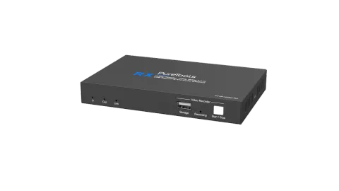
The PT-IP-HD2K is an IP Streaming Encoder/Decoder which use H.264 standard to extend HDMI video, IR and RS232 control signals over IP network. It works with one control PC (Wake on LAN) and one switch whose transmission rate is 100Mbps or higher to control a variety of functions.
The PT-IP-HD2K features 1080p HDMI video switching, video matrix, audio de-embedding, audio switching, IR&RS232 transmission, video recording, PoE, etc. The control software IP Streaming Management merge all functions for user control the IP streaming system.
Features
- Supports H.264 encoding and decoding.
- 1080p video over IP network with IR and RS232 control signals at distances up to 120m over CATx cable.
- Support video extension, video distribution and video matrix.
- Support output video scaling to 720p or 1080p.
- Supports PoE , Encoder/Decoder can be powered by PoE Switch
- Support Video Live Preview on the GUI.
- Support Video Broadcasting over network.
- Supports video recording.
- The encoder features HDMI loop out.
- Supports audio breakout.
- Supports RTSP, RTP, HTTPFLV, UDP, TCP Protocol.
- Supports Unicast and Multicast.
Package List
| PT-IP-HD2K-TX | PT-IP-HD2K-RX |
|---|---|
| 1x PT-IP-HD2K-TX Encoder (TX) | 1x PT-IP-HD2K-RX Decoder (RX) |
| 2x Mounting Ears with 2 Screws | 2x Mounting Ears with 2 Screws |
| 1x 3-pin Terminal Block | 1x 3-pin Terminal Block |
| 1x User Manual | 1x User Manual |
Specification
| PT-IP-HD2K-TX | PT-IP-HD2K-RX | |
|---|---|---|
| Video Input | (1) HDMI In | |
| Video Input Connector | (1) Type-A female HDMI | |
| HDMI Input Resolution | Up to 1080p@60Hz 444 10/12bit | |
| Video Output | (1) HDMI Out | (1) HDMI Out |
| Video Output Connector | (1) Type-A female HDMI | (1) Type-A female HDMI |
| HDMI Output Resolution | Up to 1080p@60Hz 444 10/12bit | Up to 1080p@60Hz 444 10/12bit |
| Control | (1) RS232, (1) IR In, (1) IR Out, (1) LAN (PoE) | (1) Storage, (1) RS232, (1) IR In, (1) IR Out, (1) LAN (PoE) |
| Control Connector | (1) 3-pin terminal block, (2) 3.5mm jack, (1) RJ45 | (1) Type-A USB, (1) 3-pin terminal block, (2) 3.5mm jack, (1) RJ45 |
| Audio Output | (1) Audio Out (L+R) | |
| Audio Output Connector | (1) RCA jack | |
| General | ||
| Video Encoding Standard | H.264 | H.264 |
| CATx Cable Length | Up to 120 meters | Up to 120 meters |
| External Power Supply | Input: AC 100~240V, 50/60Hz, Output: 12V DC 1A; PoE supported. | Input: AC 100~240V, 50/60Hz, Output: 12V DC 1A; PoE supported. |
| Power Consumption | Encoder:4W (Max); Decoder:3.5W (Max) | Encoder:4W (Max); Decoder:3.5W (Max) |
| Operation Temperature | -5℃ ~ +55℃ | -5℃ ~ +55℃ |
| Storage Temperature | -25℃ ~ +70℃ | -25℃ ~ +70℃ |
| Relative Humidity | 10%-90% | 10%-90% |
| Dimension (W*H*D) | 152.0mm x 21.0mm x 100.0mm | 152.0mm x 21.0mm x 100.0mm |
| Net Weight | Encoder: 340; Decoder: 345g | Encoder: 340; Decoder: 345g |
Panel Description
PT-IP-HD2K-TX Encoder
- POWER LED: The LED illuminates green when power is applied.
- In LED: The LED illuminates blue when the encoder detects HDMI source input.
- Out LED: The LED illuminates blue when the HDMI Out port is connected to display device.
- Link LED: The LED illuminates blue when there is a valid LAN link between the encoder and the network switch.
- HDMI In: Type-A female HDMI port to connect HDMI video source device.
- HDMI Out: Type-A female HDMI port to connect HDMI display device.
- RS232: 3-pin terminal block for RS232 routing control. Supports point to point unicast and point to multipoint broadcast configuration.
- IR IN: 3.5mm jack to connect an IR receiver for IR routing control.
- IR OUT: 3.5mm jack to connect an IR emitter for IR routing control.
- LAN (PoE): RJ45 port to connect directly to the decoder or a network switch using a CATx cable.
- DC 12V: DC port for AC power adapter connection.
PT-IP-HD2K-RX Decoder
- POWER LED: The LED illuminates green when power is applied.
- Out LED: The LED illuminates blue when the HDMI Out port is connected to display device.
- Link LED: The LED illuminates blue when there is a valid LAN link between the decoder and the network switch.
- Storage: Type-A USB to connect U-disk for video recording.
- Recording LED: The LED illuminates blue when recording video.
- Start/Stop Button: Press the button to start or stop video recording.
- HDMI Out: Type-A female HDMI port to connect HDMI display device.
- Audio Out: RCA jack to connect audio output device.
- RS232: 3-pin terminal block for RS232 routing control. Supports point to point unicast and point to multipoint broadcast configuration.
- IR IN: 3.5mm jack to connect an IR receiver for IR routing control.
- IR OUT: 3.5mm jack to connect an IR emitter for IR routing control.
- LAN (PoE): RJ45 port to connect directly to the encoder or a network switch using a CATx cable.
- DC 12V: DC port for AC power adapter connection.
System Connection
Connection Type
There are three types of possible applications:
Extender (Point-to-Point)
In a point-to-point configuration, there is no need for a switch. Distribute full, uncompressed data up to 1080p@60Hz resolution and RS232, IR control signals over a single Cat-x cable.
Splitter (One-to-Many)
With only one encoder and one Ethernet switch (100Mbps or higher), any A/V signal can be flawlessly and instantly distributed to a near limitless number of decoder and screens, any number of times.
Matrix Switcher (Many-to-One, Many-to-Many)
The combination of switching and splitting enables a completely scalable matrix system. Independently route video, audio and RS232, IR control signal from any source to any endpoint. The IP streaming system allows for on-the-fly upgrading and a virtually unlimited number of I/O ports.
System Diagram
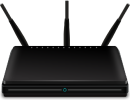
The following diagram illustrates typical input and output connections that can be utilized with the IP streaming encoder/decoder:

IP Streaming System
Control PC connection:
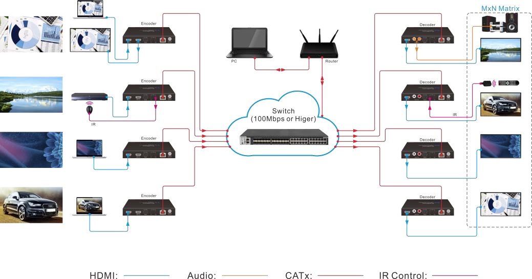
To ensure the stability of the system, a router should be connected to the system, and the control PC needs to be connected to the router or switch with a network cable instead of a wireless connection.
① PC → Router → Switch
② PC → Switch → Router
PC Router Switch(100Mbps or Higer)
PC RouterSwitch(100Mbps or Higer)
③ PC → (Wireless) Router → Switch
④ PC → Switch
Hardware Setup
- Connect the video/graphics source device to the HDMI input connector on each TX unit.
- (Optional) Connect the video display device to the HDMI output connector on each TX unit.
- Connect the video display device to the HDMI output connector on each RX unit.
- (Optional) Connect audio output device (e.g. speaker or headphone) to the audio output connector of the RX if you want to test additional audio extension.
- (Optional) Connect RS232 devices as needed if you want to test RS232 serial extension between TX and RX units.
- (Optional) Connect compatible IR emitter modules to the IR output connectors of any TX or RX.
- (Optional) Connect compatible IR receiver modules to the IR input connectors of any TX or RX.
PC Router
Wireless
Switch(100Mbps or Higer)
PC Switch(100Mbps or Higer)
- Connect an Ethernet cable (Cat-6a recommended) from the LAN port each TX and RX unit to any available LAN port.
- Connect the control PC to the LAN port of router device or to a Cat-x port of the switch (except the management/console port of the switch).
- The hardware setup is now complete.
Note: The default IP mode is DHCP, an IGMP network switch which has the function of IP distributing is needed for setting up the system. Any TX can also be connected directly to a RX without the switch using CaTx cable to feature point to point extension.
General Information
The IP Streaming Management is a control software used to configure and control signal extension, routing and switching between Encoder and Decoder units.
The IP Streaming Management can be used on any Windows PC using Microsoft .Net framework 4.0 or later Windows version.
Before proceeding ensure that the IP addresses of PC and all units are on the same local area network (LAN).
After install the control software, start the application by double clicking on PT-IP-HD2K.exe file.
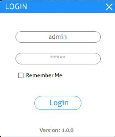
Username: admin
Password: admin
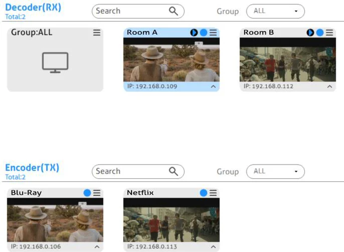
Upon launch, the IP Streaming Management main window will open up in the “Video Switching” tab as shown in the picture below:
After starting the IP Streaming Management application, it will show discovered devices as tiles. There are few things to take note of:
- The application has many different tabs for controlling the HDMI routing, as well as routing of other signals such as analog audio, RS232 control, etc. The default current tab should be "Video Switching", which means the video source displayed by an RX device (Decoder).
- The top area of the user interface is labeled "Decoder (RX)". All RX devices detected on the network will be displayed here.
- The bottom area of the user interface is labeled “Encoder (TX)". All TX devices detected on the network will be displayed here.
All connected TX and RX devices on the network will appear as a gray tile within the application window.
Each tile will identify the “Hostname” of the device. The “Hostname” can be updated at any time by “Network Setting” interface. The “IP Address” of the device is also shown in the tile.
If a source device is connected to the video port of the TX, a picture illustrating a source device will appear within the respective tile along with information about the video feed. Similarly, if a display device is connected to the RX, an illustration of a display will appear within the corresponding RX tile. If no device is visible within the tile, it means that the device is connected and detected but no source (or display) device is connected to the TX (RX).
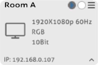
TX device tile info
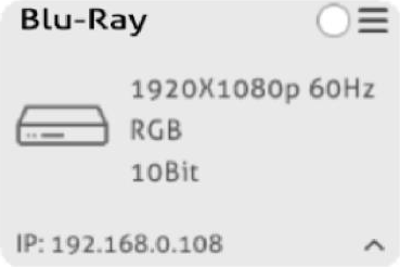
RX device tile info
Hostname
Streaming/Stopped Status
Setting Menu
Video Resolution
More Information
Color Space
IP Address
General Setting
Click on at the bottom-left corner to enter system setting interface.
Basic Setting:
- LogOut: Click the button to exit the current login account.
- Initial Page: Select initial interface for system operating easily.
- Factory Reset All: Click “Factory Reset” to restore all Encoders and Decoders to factory settings.
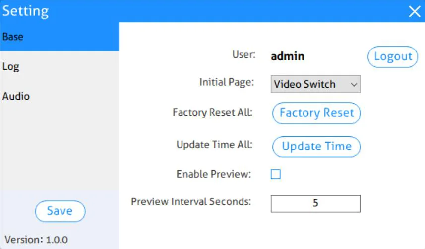
- Update Time All: Click “Update Time” to set the time of all connected Encoders and Decoders to synchronize with computer time.
- Enable Preview: Enable video preview function, the Encoder/Decoder title on the “Video Switching” will display the video image as shown below:
- Preview Interval Seconds: Set the refresh time of video preview.
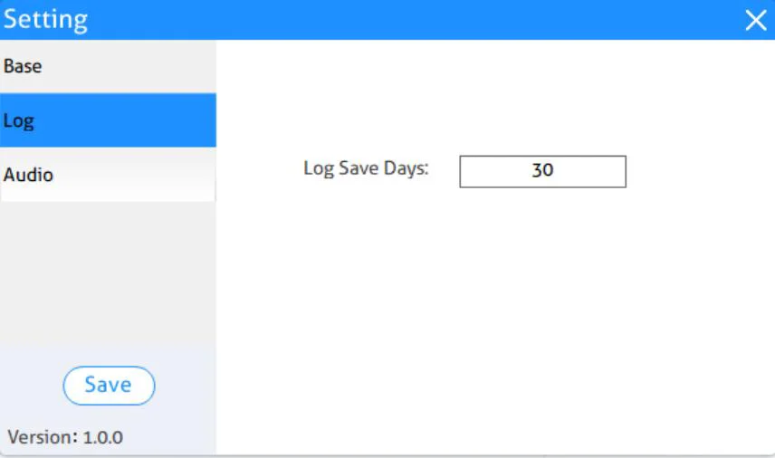
Log Setting:
- Log Save Days: Set the number of days to save the software log.
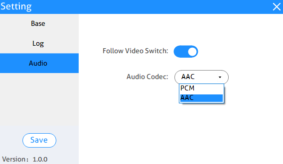
Audio Setting:
- Follow Video Switch: Enable the function of audio follow video switching. When switching video signal at Video Switching tab, the audio will automatically follow the video switch. Note that it is invalid that switch audio separately at Audio Switching tab.
- Audio Codec: Set the audio coding standard to AAC or PCM for all encoders.
Video Routing Tab
The "Video Switching" tab is used to manage signal routing between TX and RX devices.
All RX devices are listed in the top half of the "Decoder (RX)" section. Similarly, all TX devices are listed in the bottom half, in the "Encoder (TX)" section.
Video Switching
- In the Encoder (TX) section, using the left mouse button to select a TX by clicking on its associated active tile.
- Hold down the left mouse button and drag the TX tile over the RX tile it is to be joined with. Then release the mouse button to drop the TX tile onto the RX tile.
- TX and RX are now joined.
The video source connected to the Encoder (TX) now appears on the display connected to the respective Decoder (RX).
Note: If the video is not being displayed, please verify the following:Ensure that the network switch has been properly configured.Confirm that the display can support the input source resolution.Verify that the HDMI cable being used is of good quality. This is particularly important for high-bandwidths of up to 1080p@60Hz resolution, requiring a "HDMI Premium High Speed" cable.
To assign a different input source to a Decoder (RX), repeat the steps mentioned above, dragging a different TX over an RX to associate the decoder itself to the new source device.
Video Recording
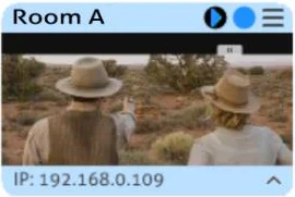
- Plug a storage device (e.g. U-disk) to the “Storage (Type-A USB)” port of Decoder (RX).
- Press the “Start/Stop” button on the front panel of Decoder (RX) or left-click the “Start/Stop” icon on the Decoder (RX) title as below.
- After starting video recording, the “Recording” LED on the front panel of Decoder (RX) will illuminate blue.
- Click the “Start/Stop” icon again to stop video recording, and the “Recording” LED will go out.
- Wait at least 1 minute, and then remove the U-disk.
Note: The recorded video format is MP4, and the video details show that the sound has only one channel, but the audio output (PCM) of the device is two channels.
Start/Stop
Video Recording
Note: The storage device format needs to support exFAT, FAT32 or NTFS.
Click the menu icon of the respective RX tile, and then click "Video File Management" can enter the interface to manage video recording file.
When the bit rate of TX is greater than 20Mbps and the bandwidth of the input source is relatively large (1080p@60Hz, about 148MHz), the recorded audio and video of RX are slightly out of sync, and the audio will be a bit delayed (less than 1s).
Sending Single Source to All RX Devices
To send the same source signal input to all receivers at the same time, simply drag and drop the TX unit that the desired source is connected to onto the blue tile in the Decoder (RX) section, labeled "Group: ALL".
Comment: To verify, which RX and TX are joined together, click on the Decoder (RX) or Encoder (TX) tile you want to see the connection status for. All the joined tiles will be highlighted in blue.
Disconnecting Source from RX
To disconnect a Decoder (RX) from an Encoder (TX) source, click the menu icon of the respective RX tile and select "Leave Video Channel".

After disconnecting source from Decoder (RX), the display device will display “No Video” as shown in the below:
Preset Management
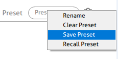
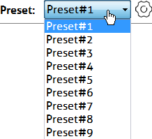
To rename a preset, delete a stored preset or save the current video switching setting, recall a saved preset by selecting “Preset #1~9” and click the gear icon to select the desired option: “Rename”, “Clear Preset”, “Save Preset”, “Recall Preset”.
Video Preview Tab
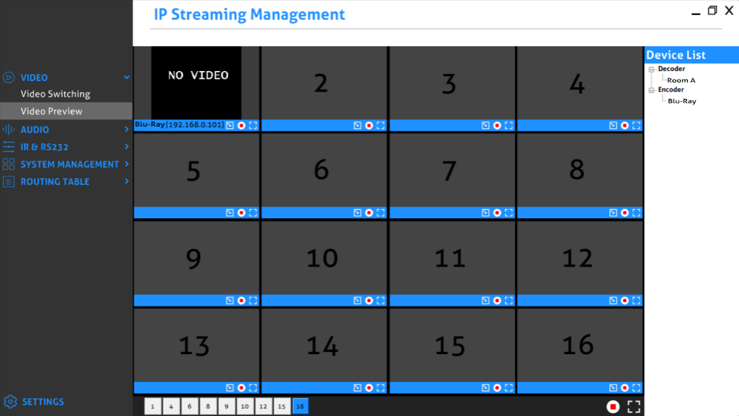
The "Video Preview" tab is used to preview video signal of all TX and RX devices, and up to 16 screens to display video.
All encoders and decoders show on the device list on the right sidebar block.
Drag and drop the desired encoder/decoder unit over the screen block it is to be displayed.
Full screen.
Shrink screen.
Clear the current screen.
The product uses H.264 standard, so the application “VLC Media Player (Downloaded from website)” can be installed in the control PC for previewing video in higher definition.
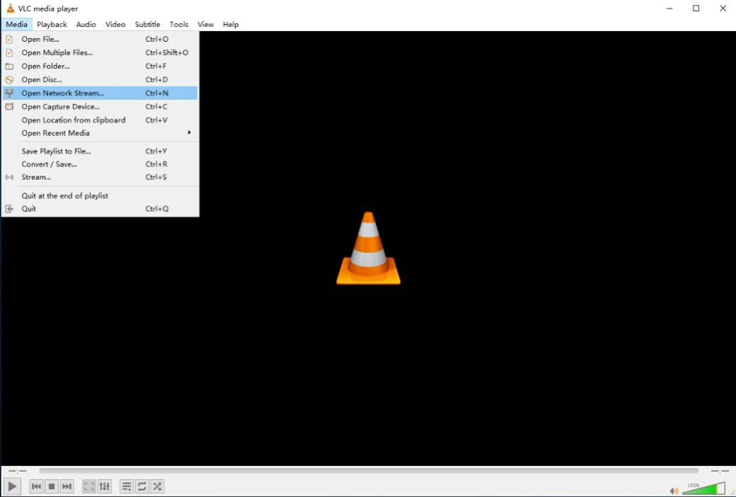
- After installing “VLC Media Player”, double click to open it and then click “Media”
and select “Open Network Streaming”.
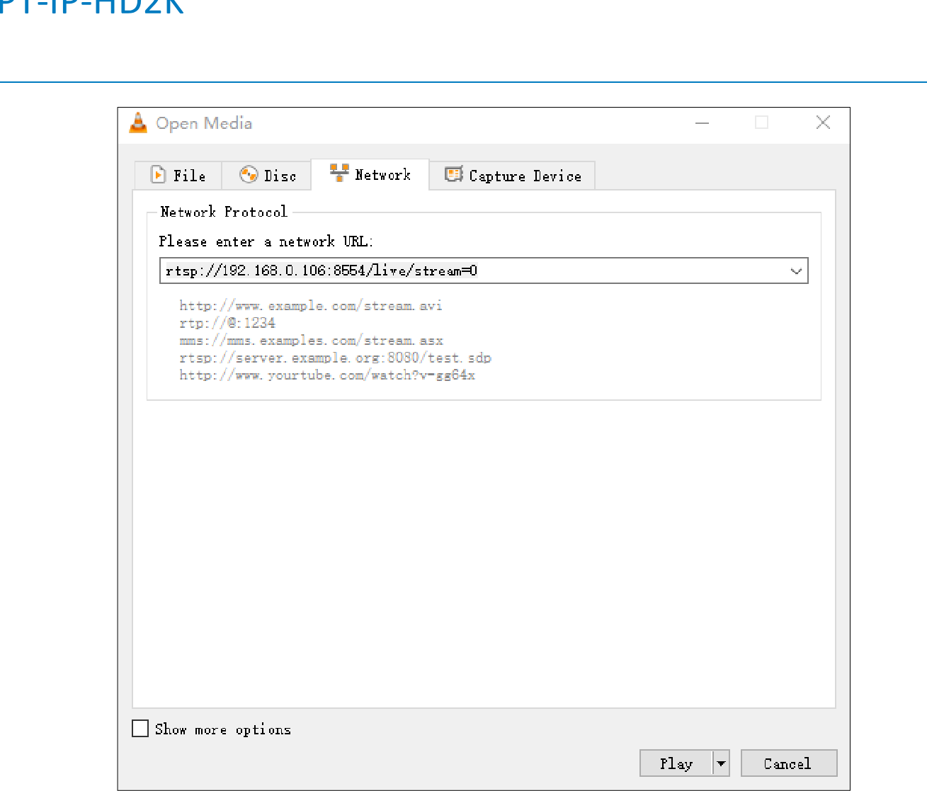
- Click “Network” and enter a network URL of desired encode, and then click “Play”.
Network URL example: rtsp://192.168.0.106:8554/live/stream=0
The “192.168.0.106” of network URL can be modified according the IP address of different encoder.
Open Media dialog showing a network stream URL input in VLC media player
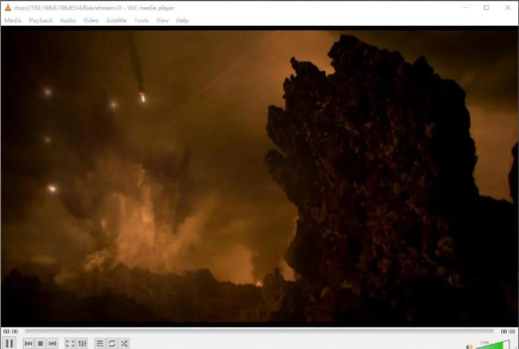
VLC media player window playing a video stream from the entered network URL
Note: When the VLC media player plays a video, if there is no sound, the audio encoding standard of the encoder can be set to AAC at “Audio Setting” tab. Please refer to the 5.8.2.1. Device Setting.
Audio Routing Tab
The "Audio Switching" tab is used to setup and manage audio routing between TX and RX devices. All the RX devices are listed in the top half of the Decoder (RX) section. Similarly, all the TX devices are listed in the bottom half in the Encoder (TX) section.
First, verify if appropriate TX and RX devices are joined:
- Verify that the Decoder (RX) is currently joined with the desired Encoder (TX).
- Click on the RX and the Encoder (TX), it will be highlighted in blue when joined to.
- Selecting the respective encoder will highlight all the decoders joined to the same TX.
If the respective Encoder (TX) is currently not joined to the Decoder (RX), join them together:
- In the Encoder (TX) section, select a TX by clicking on its associated active tile.
- Drag and drop the TX tile onto the RX tile to which it is attached.
- TX and RX are now joined together.
- Repeat above steps if additional decoders are to be joined to the same TX.
RS232 Routing Tab
The "RS232 Routing" tab is used to setup and manage RS232 data distribution for devices. There are two sections provided in the IP Streaming Management interface, "Encoders (TX)" and "Decoders (RX)". Each device discovered on the network is listed in both groups, because each of them can send and receive RS232 data.
- Select the "RS232 Routing" tab in the IP Streaming Management interface.
- Verify which Encoders and Decoders are joined together. Click on the device tile whose connection status you want to see. All joined together tiles will be highlighted blue.
- To pair devices, drag the tile representing the Encoder (TX) and drop it over the desired Decoder (RX) to create one-way communication.
- To create a bi-directional RS232 path on a pair of Encoder (TX) and Decoder (RX), two separate pairings are required. Repeat the step above, but in reverse (drop TX on RX) to create the second pairing.
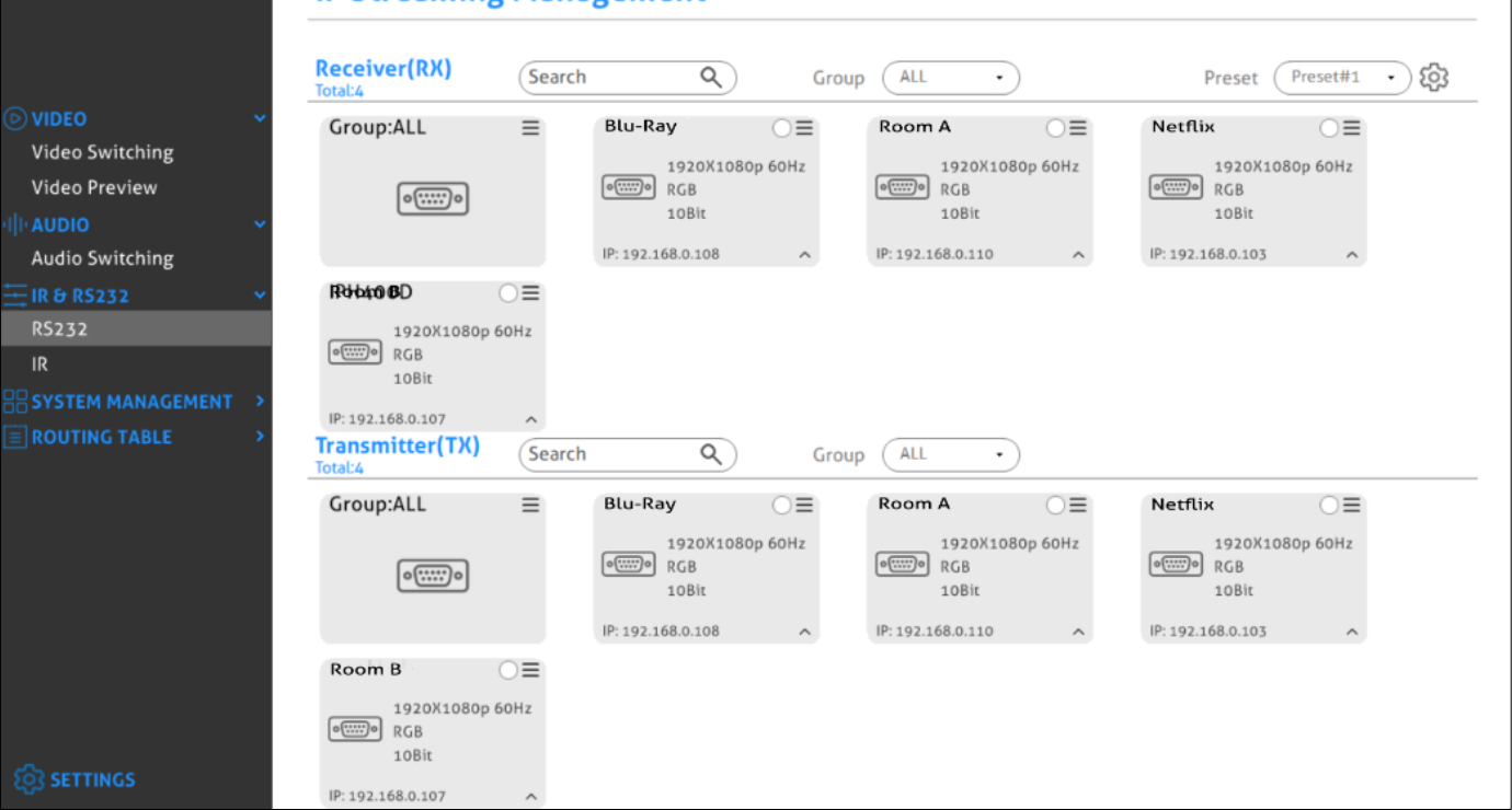
Assign Encoder to all Decoders
To distribute RS232 data from a single encoder to all decoders, drag and drop the respective encoder's tile onto the tile labeled "Group: ALL" in the "Decoders" section of the "RS232 Routing" tab.
Sending RS232 Data from IP Streaming Management to a Third-party Device
- Click menu icon of the respective encoder or decoder tile.
- Select "Device Options".
- Select "Send/Receive RS232".
- A dialog box opens.
- Enter the RS232 string you want to send.
- Click the "Send" button to send out the string.
- Paired devices will receive the RS232 command.
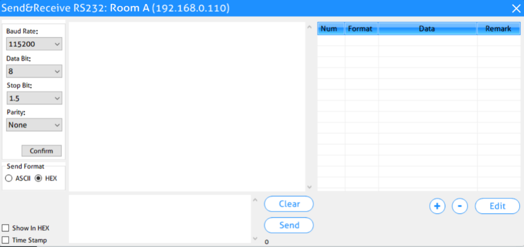
IR Routing Tab
The "IR Routing" tab is used to setup and manage IR data distribution for devices. There are two sections provided in the IP Streaming Management interface, "Encoders (TX)" and "Decoders (RX)". Each device discovered on the network is listed in both groups, because each can both send and receive IR data.
- Select the "IR Routing" tab in the IP Streaming Management interface.
- Verify, which Encoders and Decoders are joined together. Click on the device tile you want to see the connection status of. All joined together tiles will be highlighted blue.
- To pair devices, drag the tile representing the Encoder (TX) and drop it over the desired Decoder (RX) to create one-way communication.
- To create a bi-directional IR path on a pair of Encoder (TX) and Decoder (RX), two separate pairings are required. Repeat the step above, but in reverse (drop TX on RX) to create the second pairing.
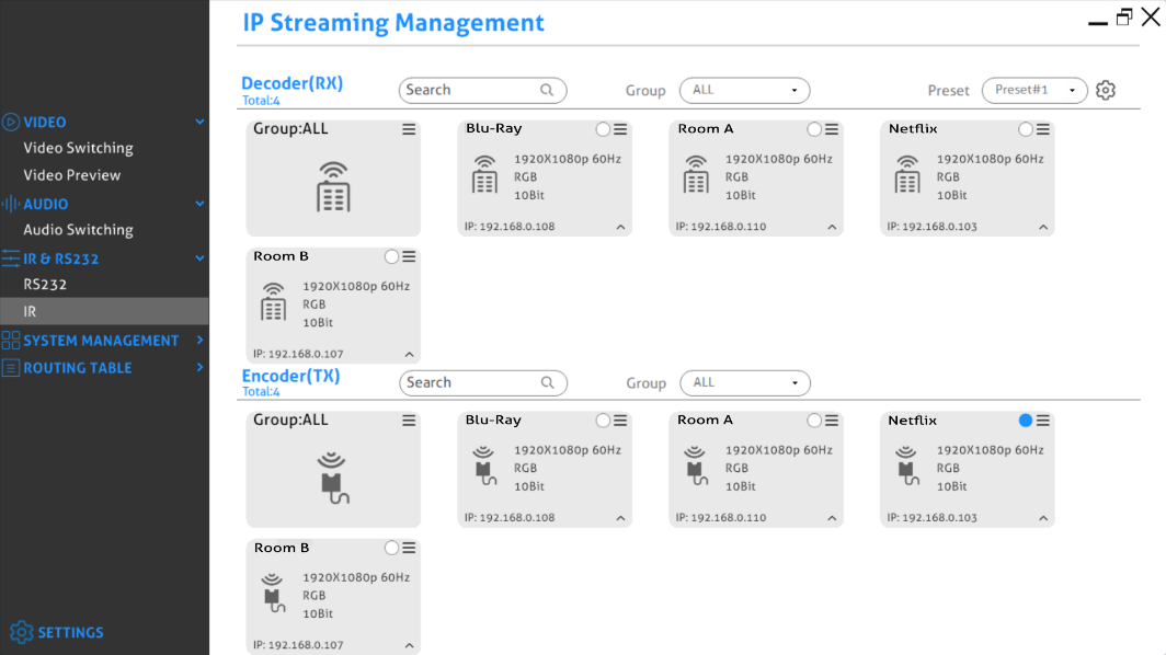
Assign Encoder to all Decoders
To distribute IR data from a single encoder to all decoders, drag and drop the respective encoder’s tile onto the tile labeled "Group ALL" in the "Decoders" section of the "IR Routing" tab.
Sending IR Data from IP Streaming Management to a Third-party Device
- Click menu icon of the respective encoder or decoder tile.
- Select "Device Options".
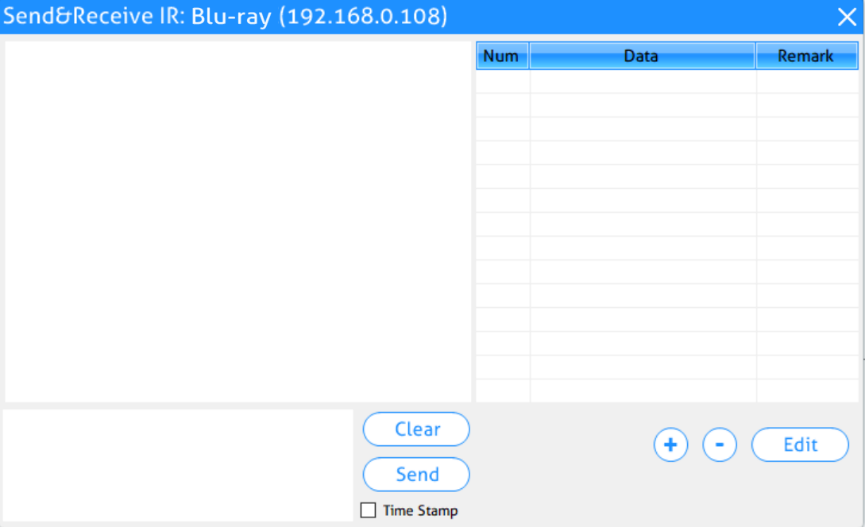
- Select "Send/Receive IR".
- A dialog box opens.
- Enter the IR string you want to send.
- Click the "Send" button to send out the string.
- Paired devices will receive the IR command.
Infrared Limitations
A Sender can either send IR data to a specific device (unicast) or broadcast to all devices active on the network (broadcast). Should be noted however, that a sender cannot send data simultaneously to a range of devices using multi-unicast.
The data format used when sending IR data from control layer to a device is ‘Pronto’. The link below points to a good description of Pronto format definition with examples.
http://www.remotecentral.com/features/irdisp1.htm
The pronto format is a series of hex numbers that describe everything that is needed to generate the required waveform. It includes the carrier frequency, the ON/OFF period along with data and error checksum.
Large libraries of Pronto IR codes are publicly available and easy to find on the Web. The code below is a Pronto string to turn Sony BlueRay player ON and OFF
0000 0067 0000 0015 0060 0018 0030 0018 0018 0018 0030 0018 0018 0018
0030 0018 0018 0018 0018 0018 0018 0018 0030 0018 0018 0018 0030 0018
0030 0018 0018 0018 0030 0018 0018 0018 0018 0018 0018 0018 0030 0018
0030 0018 0030 01FE.
Global Command Options and Settings
To access a device’s options, click the menu icon of any connected TX or RX.
Note: Device options can be accessed from any detected device and from any of the interface tabs, "Video Switching", "Audio Switching", etc.
Decoder (RX) Settings Options
The following section illustrates the Decoder (RX) device settings dialog box.
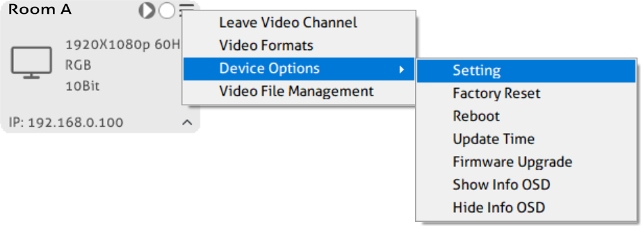
- Leave Video Channel: Disconnect the Decoder (RX) from an Encoder (TX) source.
- Video Formats: Set the video format of the decoder.
- Device Setting: Analog Audio Setting, Network Setting and External Storage Setting.
- Factory Reset: Restore the decoder to factory settings.
- Reboot: Reboot the decoder.
- Update Time: Update the device time to let it same with the control PC.
- Firmware Upgrade: Update firmware version of decoder.
- Show Info OSD: Show the device information of decoder on display.
- Hide Info OSD: Hide the device information of decoder on display.
- Video File Management: Manage and download the video recording files.
Video Format Setting
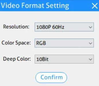
To set the video format of decoder, click the menu icon of the respective RX tile and select "Video Formats". The following resolution, color space, Deep Color can be selected:
| Video Resolution | Color Space | Deep Color |
|---|---|---|
| 1080p@25Hz, 1080p@30Hz, 1080p@50Hz, 1080p@60Hz (Default), 720p@50Hz, 720p@60Hz, 1080I@50Hz, 1080I@60Hz | RGB, YCbCr 4:4:4 | 10Bit, 12Bit |
Device Setting
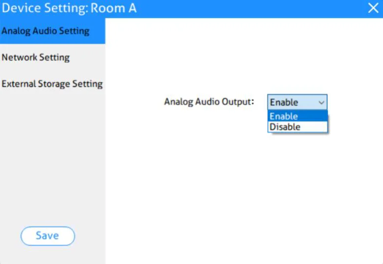
Click the menu icon of the respective RX tile and click "Device Options", then select “Setting” to enter the below device setting interface.
Analog Audio Setting: Select “Enable/Disable” to turn on/off the analog audio output of decoder.
Network Setting: Use this tab to modify the device's host name and configure the IP address.
To rename a device, enter a name (e. g. “PT-IP-HD2K-RX-1”) into the "Host Name" edit box. Press the "Save" button to save the new host name. The host name is persistent and kept until the device is forced back to factory defaults.
The IP address can be set to be either "DHCP" or "Manual".
- Select "DHCP" to receive the IP address from a DHCP server or to be auto-assigned with an IP from the 169.254.X.X range, in case there is no DHCP server on the network.
- Select "Manual" to set a static IP address (IPV4 address, subnet mask and gateway address).
Press "Save" to save the new IP address. The new IP mode settings are stored in non-volatile memory and kept, until the device is forced back to factory defaults.
Note: Special attention is required, when assigning a manual IP address. The address has to be both unique and reachable. Any mistake when entering the IP address, subnet mask or gateway address can render the device unreachable.
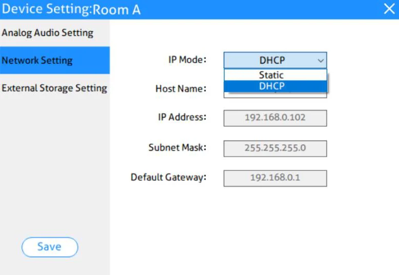
External Storage Setting: Use this tab to set the video recording type to “Stop recording when storage is full” or “Overwritten recording when storage is full”.
Click “Formatting” to format the video storage device.
Factory Reset
Click the menu icon of the respective RX tile and click "Device Options", then click “Factory Reset” to open prompt box. Click “Yes” to restore factory default.
Device Reboot
Click the menu icon of the respective RX tile and click "Device Options", then click “Reboot” to open prompt box. Click “Yes” to reboot the device.
Firmware Upgrade
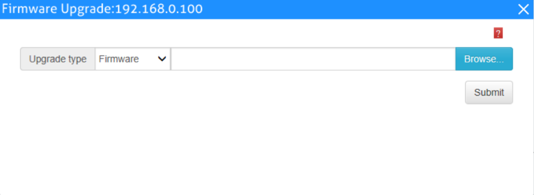
Click the menu icon of the respective RX tile and click "Device Options", then click “Firmware Upgrade” to enter the below interface. Select upgrade type and click “Browse” to add the update file, and then click “Submit” to start the firmware upgrade.
Video File Management
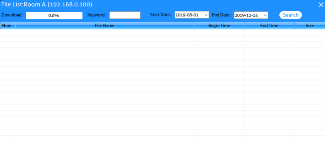
Click the menu icon of the respective RX tile, and then click "Video File Management" to enter the below interface to manage video recording files.
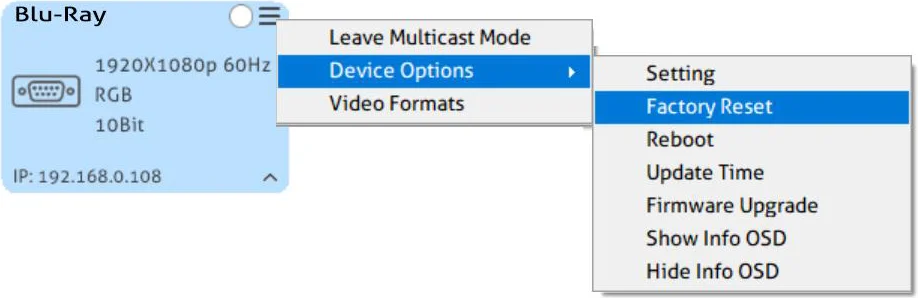
Encoder (TX) Settings Options
The following section illustrates the Encoder (TX) device's settings dialog box.
- Leave Multicast Mode: Exit multicast mode.
- Device Setting: Network Setting and Audio Setting.
- Factory Reset: Restore factory default.
- Reboot: Reboot the encoder.
- Update Time: Update the device time to let it same with the control PC.
- Firmware Upgrade: Update firmware version of encoder.
- Show Info OSD: Show the device information of encoder on display.
- Hide Info OSD: Hide the device information of encoder on display.
- Video Formats: Set the video format of the encoder.
Device Setting
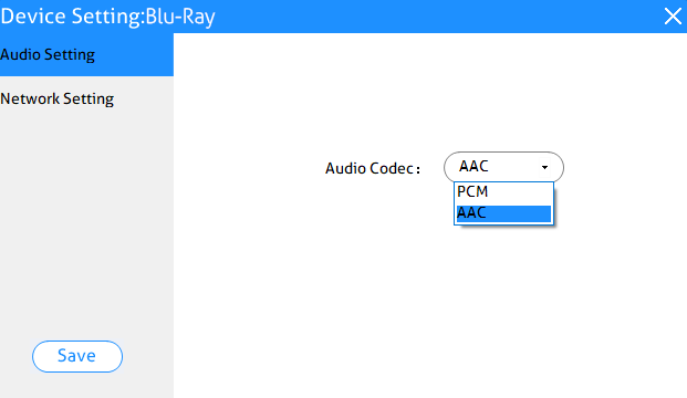
Click the menu icon of the respective TX tile and click "Device Options", then select “Setting” to enter the below setting interface.
Audio Setting: Use this tab to set the audio coding standard of the encoder to AAC or PCM.
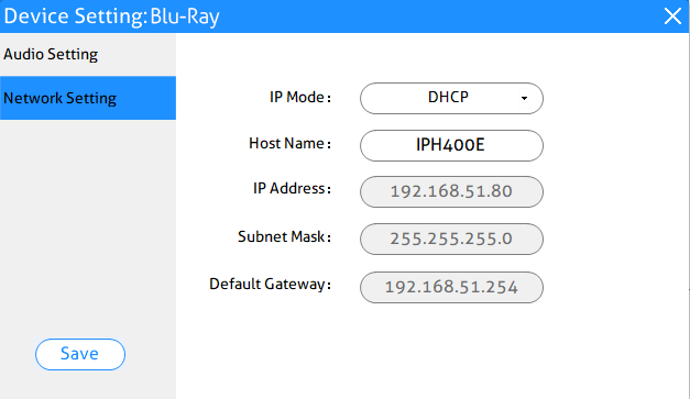
To rename a device, enter a name (e.g. “PT-IP-HD2K-TX-1”) into the Host Name edit box. Press the “Save” button to save the new host name. The host name is persistent and kept until the device is forced back to factory defaults.
The IP address can be set to be either DHCP or Manual.
- Select “DHCP” to receive the IP address from a DHCP server or to be auto-assigned with an IP from the 192.168.X.X range, in case there is no DHCP server on the network.
- Select “STATIC” to set a static IP address (IPV4 address, subnet mask and gateway address).
Video Format Setting
To set the video format of encoder, click the menu icon of the respective TX tile and
select “Video Formats”.
The following resolution, color space, Deep Color can be selected:
| Video Resolution | Color Space | Deep Color |
|---|---|---|
| 1080p@25Hz, 1080p@30Hz, 1080p@50Hz, 1080p@60Hz (Default), 720p@50Hz, 720p@60Hz, 1080I@50Hz, 1080I@60Hz | RGB, YCbCr 4:4:4 | 10Bit, 12Bit |
Factory Reset
Click the menu icon of the respective TX tile and click “Device Options”, then click “Factory Reset” to open prompt box. Click “Yes” to restore factory default.
Device Reboot
Click the menu icon of the respective TX tile and click “Device Options”, then click “Reboot” to open prompt box. Click “Yes” to reboot the device.
Firmware Upgrade
Click the menu icon of the respective TX tile and click “Device Options”, then click “Firmware Upgrade” to enter the below interface. Select upgrade type and click “Browse” to add the update file, and then click “Submit”
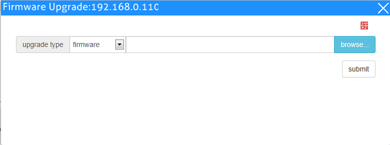
to start the firmware upgrade.
System Management Tab
Security Settings
Select the “Security” tab in the IP Streaming Management interface to enter the section for modifying the password.
- Click “New” to add new user account and set its access permission.
- Select one account on the list, and then click “Change” to reset password.
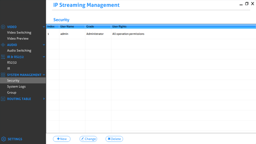
- Select one account on the list, and then click “Delete” to delete the selected user.
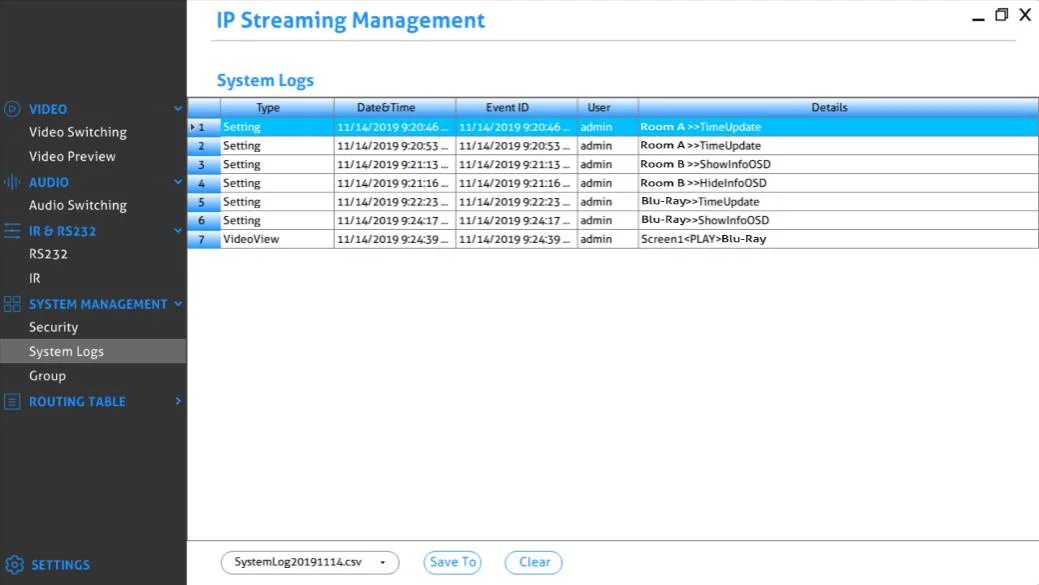
System Logs
Select the “System Logs” tab in the IP Streaming Management interface to enter the section for inquiring the system logs.
- Select system log file, and then click “Save To” to save the log file, or click “Clear” to delete the selected log file.
Group Management
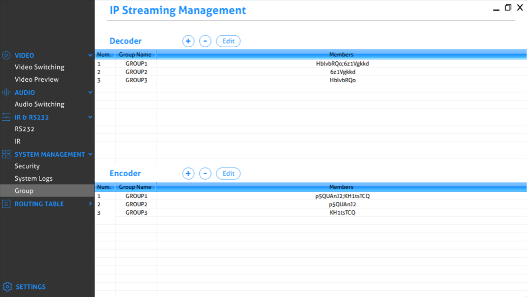
Select the “Group” tab in the IP Streaming Management interface to enter the section for group setting.
- Click “+” to add new group.
- Select one group on the list, and then click “-” to delete the group.
- Select one group on the list, and then click “Edit” to set the group.
Routing Table
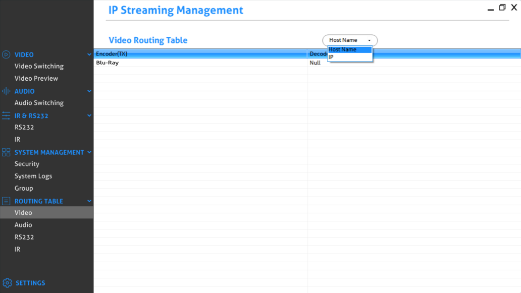
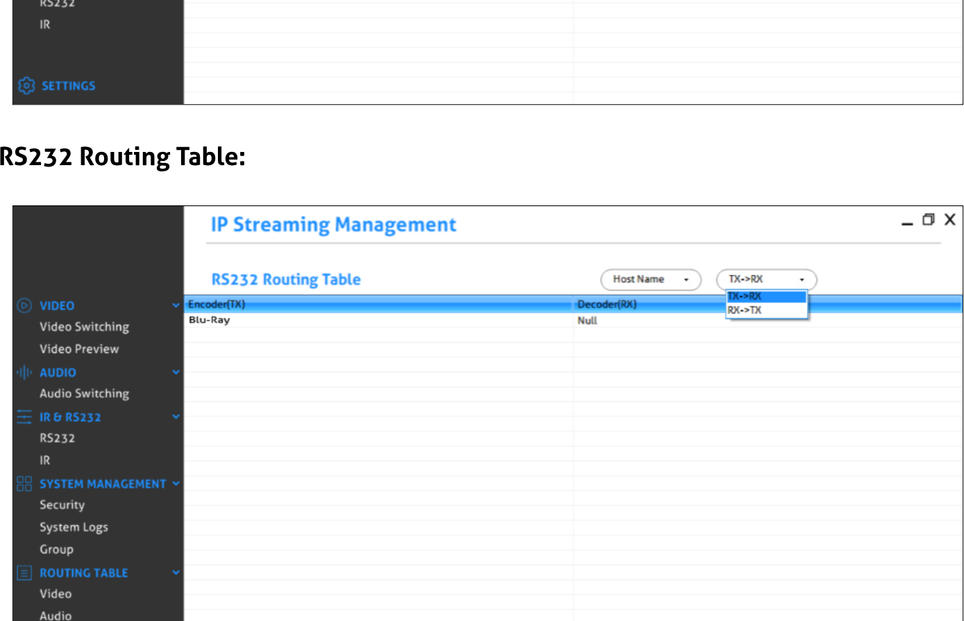
The routing table allows to gather info about the video, HDMI audio, analog audio and RS232 routing status.
Video Routing Table:
Audio Routing Table:
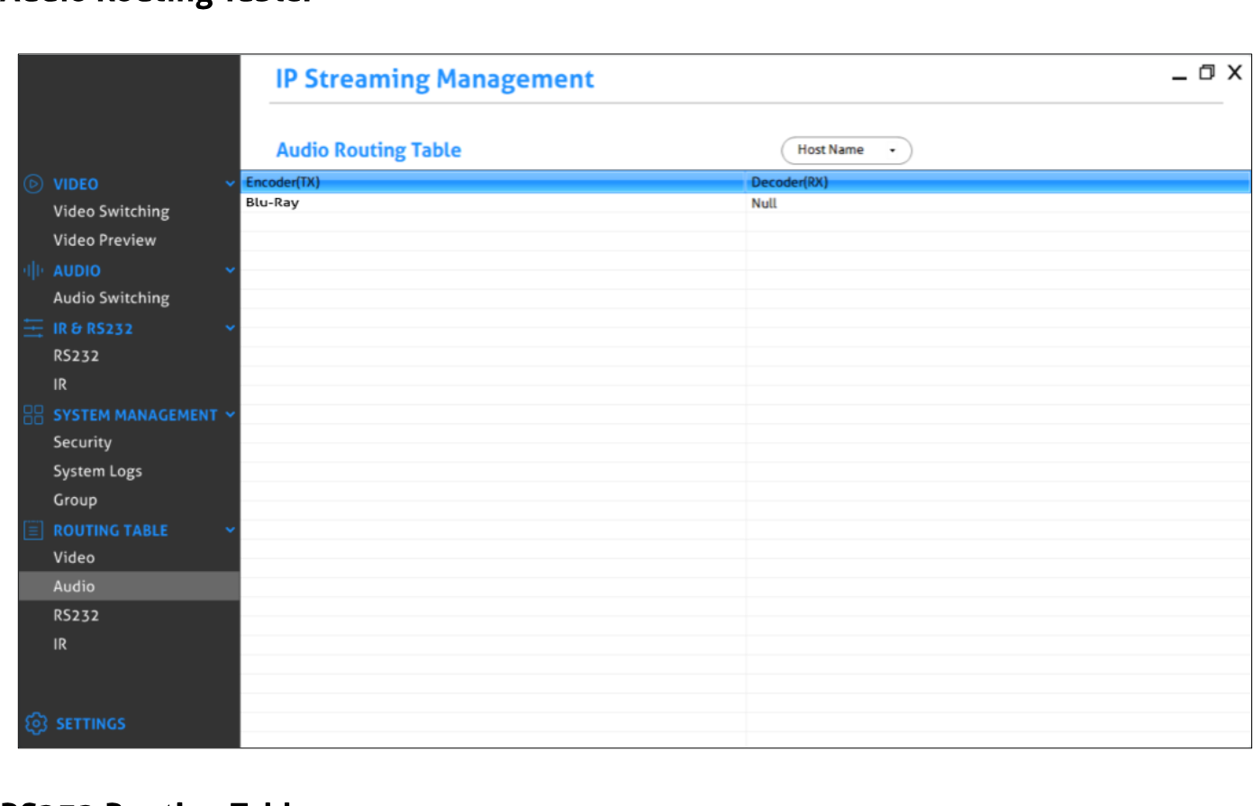
Audio Routing Table screenshot
RS232 Routing Table:
RS232 Routing Table screenshot
IR Routing Table:
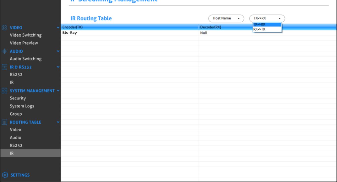
IP Streaming Management IR Routing Table screenshot
After-Sales Service
If problems appear when using the product, please deal with the problems referring to this user manual. During the warranty period, any transport costs are borne by the customer.
- Product Limited Warranty: The product will be free from defects in materials and workmanship for two years (The purchase invoice shall prevail). Proof of purchase in the form of a bill of sale or receipted invoice which is evidence that the unit is within the Warranty period must be presented to obtain warranty service.
- What the warranty does not cover (servicing available for a fee):
- Technical Support: For any questions or problems, contact your distributor or reseller and tell them the respective product name and version, the detailed failure situation as well as the formation of the cases.
- Warranty expiration.
- Factory applied serial number has been altered or removed from the product.
- Damage, deterioration or malfunction caused by:
- Normal wear and tear.
- Use of supplies or parts not meeting our specifications.
- No certificate or invoice as the proof of warranty.
- The product model shown on the warranty card does not match with the model of the product for repairing or had been altered.
- Damage caused by force majeure.
- Servicing not authorized by distributor.
- Any other causes which does not relate to a product defect.
- Delivery, installation or labor charges for installation or setup of the product.
Legal & Compliance
Product identification
Models: PT-IP-HD2K-RX, PT-IP-HD2K-TX – manual version 1.0
Trademarks and disclaimer
Product model and logo are trademarks. All other company and product names mentioned are trademarks of their respective owners. All rights reserved. No part of this publication may be copied or reproduced without prior written permission. We reserve the right to make changes to the device, packaging or manual and accept no liability for misprints.
FCC
Statement This equipment generates, uses and can radiate radio frequency energy and, if not installed and used in accordance with the instructions, may cause harmful interference to radio communications. It has been tested and found to comply with the limits for a Class B digital device, pursuant to part 15 of the FCC Rules. These limits are designed to provide reasonable protection against harmful interference in a commercial installation.
Disposal of electrical and electronic equipment
WEEE reg. no.: DE 93847290
The crossed-out wheelie bin symbol on the product, packaging or in this manual means that electrical and electronic equipment must not be disposed of with household waste at the end of its life. Hand in old devices free of charge at a public collection point or return them to a distributor obliged to take them back. Remove batteries and lamps that can be removed without destroying the device before handing it in, and delete any personal data stored on the device. Details are regulated by national law. By returning old devices you help protect the environment.
Packaging
Dispose of packaging separately by material (paper/cardboard, plastics) via the local collection systems. Keep packaging material away from children – risk of suffocation. Packaging register LUCID: DE5958616449295.