
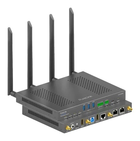
Introduction
The switcher is a high-performance BYOD presentation switcher with wireless presentation capability. It equips built-in Wi-Fi modules and offers multiple access approaches, including Airplay Mirroring, Miracast, Dongle and physical HDMI and USB-C ports, with which you can project the screen contents of your computers (Mac/Windows) or mobile devices (iPhone/iPad/Android phone) to the display in dual view. Multiple features like automatic signal switching, USB switcher, CEC, Guide Screen, and OSD are also included. The switcher is a collaboration terminal used for meeting room or workgroup discussion.
General Notes
Please read this user manual in its entirety and carefully. It forms part of the product and contains important notes for operating and storing. Please keep this document in a safe place for other users or for personal reference.
This product is intended for indoor use only. Please do not use it in any outdoor areas. Any contact with water and moisture must be avoided under all circumstances.
For product safety and compliance purposes (CE), please do not rebuild and/or modify this product. Please note that if you use the product for purposes other than those described above, the product may be damaged. In addition, improper use can cause hazards such as short circuiting, fire, electric shock, etc.
Safety Instructions
Read the operating instructions carefully and especially observe the safety information. If you do not follow the safety instructions and information on proper handling in this manual, we assume no liability for any resulting personal injury or damage to property. Such cases will invalidate the warranty/guarantee.
Electrical Safety
Ensure that the product is connected to a power source that matches the specifications provided in the user manual. Do not expose the product to water or moisture to prevent electrical shock or damage.
Mains Cable Usage
Only use the product with the supplied accessories. Do not attempt to modify or replace it.
Usage
Only use the product for the intended use case described in this user manual.
Maintenance
Regularly clean the product with a soft, dry cloth to maintain the correct function. Do not attempt to disassemble or repair the product yourself. Contact customer support for any issues.
Children and Pets
Keep the products, the accessories and the packaging out of reach of children and pets to prevent accidental injury or damage.
Unattended Operation
Do not leave the product unattended while it’s being used. Turn off/unplug the product when not in use.
Authorized Service
Only authorized personnel should perform repairs or modifications to the product. Contact customer support for assistance.
Emergency Disconnect
In case of any unusual behavior (e.g., overheating, smoke), immediately disconnect the product from the power source and contact customer support.
Storage
When not in use, store the product in a cool, dry place away from direct sunlight and extreme temperatures.
Delivery Contents
- 1x Presentation Switcher
- 4x Wi-Fi Antennas
- 1x DC 20V 6A Power Adapter
- 1x EU AC Power Cable
- 1x 3.5mm 3-Pin Phoenix Male Connector
- 1x 3.5mm 5-Pin Phoenix Male Connector
- 4x Mounting Brackets
- 4x Screws
Features
- Provides one USB-C input, one HDMI input, one HDMI output and one HDBT output that mirrors the HDMI output.
- USB-C Input supports USB-C input, charging up to 60W, Ethernet connection, and USB 3.0.
- Video outputs support dual view presentation.
- Supports input resolutions up to 4K 30Hz 4:4:4.
- Supports output resolutions up to 4K 60Hz 4:4:4 (4:2:0 for HDBT output).
- Fast seamless switching for both single and dual view layouts.
- Independent analog audio output.
- Built-in Wi-Fi modules for wireless connectivity with devices over Airplay Mirroring, Miracast, Dongle and Chromecast.
- Supports wireless conference (using Dongle for connecting between the host PC and USB conference peripherals wirelessly).
- Built-in triple USB 3.0 switcher allows for USB switching among three USB hosts (two wired, one wireless).
- Two Ethernet ports for networking flexibility and security.
- Detailed and friendly OSD information.
- Flexible control approaches of Web UI, Telnet API, RS232.
- Note: Chromecast feature will be available in further firmware version soon.
Specifications
Video
| Input Video Port | 1x USB-C 1x HDMI 2x LAN 2x Wi-Fi |
|---|---|
| Input Video Signal | HDMI: HDMI 1.4, HDCP 1.4 USB-C: DisplayPort 1.1, HDCP 1.4 LAN/Wi-Fi: H.264 |
| Input Resolutions | USB-C/HDMI: 640x4808, 720x4808 (480p), 720x5766 (576p), 800x6008, 1024x7688, 1280x7688, 1280x8008, 1280x10248, 1360x7688, 1366x7688, 1440x9008, 1400x10508, 1600x12008, 1680x10508, 1920x12008, 1280x7205 (720p30), 1280x7206 (720p50), 1280x7208 (720p60), 1920x10802 (1080p24), 1920x10803 (1080p25), 1920x10805 (1080p30), 1920x10806 (1080p50), 1920x10808 (1080p60), 3840x21605 (2160p30) Miracast (Wi-Fi): 640x4808, 720x4808 (480p), 720x5766 (576p), 1280x7202, 1280x7203, 1280x7205 (720p30), 1280x7206 (720p50), 1280x7208 (720p60), 1920x10802 (1080p24), 1920x10803 (1080p25), 1920x10805 (1080p30), 1920x10806 (1080p50), 1920x10808 (1080p60) Airplay Mirroring (LAN/Wi-Fi): Up to 1920x10808 (1080p60) *Chromecast (LAN/Wi-Fi): Up to 1920x10805 (1080p30) USB-C Dongle: 1920x10808 (1080p60), 3840x21605 (2160p30) 1 = 23.98Hz, 2 = 24Hz, 3 = 25Hz, 4 = 29.97Hz, 5 = 30Hz, 6 = 50Hz, 7 = 59.94Hz, 8 = 60Hz |
| Output Video Port | 1x HDMI, 1x HDBT |
|---|---|
| Output Video Signal | HDMI OUT: HDMI 2.0, HDCP 2.2 HDBT: HDMI 1.4, HDCP 1.4 |
| Output Resolutions | HDMI OUT: 640x4808, 720x4808 (480p60), 720x5766 (576p60), 800x6008, 1024x7688, 1280x7206 (720p50), 1280x7208 (720p60), 1280x8008, 1280x10248, 1366x7688, 1440x9008, 1600x12008, 1680x10508, 1920x12008, 1920x21605, 2560x14405, 2560x14408, 2560x16008, 1920x10802 (1080p24), 1920x10803 (1080p25), 1920x10805 (1080p30), 1920x10806 (1080p50), 1920x10808 (1080p60), 3840x21603 (2160p25), 3840x21605 (2160p30), 3840x21606 (2160p50), 3840x21608 (2160p60) HDBT: 640x4808, 720x4808(480p60), 720x5766(576p60), 800x6008, 1024x7688, 1280x7206(720p50), 1280x8008, 1280x10248, 1366x7688, 1440x9008, 1600x12008, 1680x10508, 1920x12008, 1280x7208(720p60), 1920x10802(1080p24), 1920x10803 (1080p25), 1920x10805(1080p30), 1920x10806(1080p50), 1920x10808(1080p60), 3840x21603(2160p25), 3840x21605 (2160p30), 3840x21606(4:2:0 2160p50), 3840x21608(4:2:0 2160p60) 1 = 23.98Hz, 2 = 24Hz, 3 = 25Hz, 4 = 29.97Hz, 5 = at 30Hz, 6 = 50Hz, 7 = 59.94Hz, 8 = 60Hz |
Note: *Chromecast will be available in further firmware version soon.
Panel Description
- Power LED On: The device is powered on. Off: The device is powered off.
- Status LED On: The switcher is working properly. Off: The switcher is in standby state.
- USB-C IN On: The corresponding video source is valid and being output. Blinking: The corresponding video source is being output but not valid. Off: The corresponding video source is neither being output nor valid.
- HDMI IN
- USB 3.0 3x USB 3.0 Type-A ports for the following two functions: 1. Connect to USB peripherals (e.g. keyboard, mouse, touch screen, camera, speakerphone, etc.) for USB expansion. Tip: Each USB-A port outputs up to 1A current. 2. Connect to a USB flash drive for firmware upgrade. More information, see Firmware Upgrade section
- AUDIO OUT 5-pin 3.5mm phoenix connector. Connect to an audio receiver for balanced analog audio output.
- RS232 3-pin 3.5mm phoenix connector for the following two functions: • Connect to a peripheral (e.g. a projector) to control the peripheral. • Connect to a controller (e.g. a computer) to control this device.
- PAIRING USB-C port. Connect to Dongle for pairing or upgrading Dongle.
- RESET A recessed button that provides two functions: • Short press the button to show OSD (On-Screen Display) on the attached display. • Press and hold the button for at least five seconds and then release, the device will automatically reboot and restore to its factory defaults.

- Wi-Fi Connect to the four Wi-Fi antennas for the access to Miracast and soft AP function.
- 20V Connect to the DC 20V power adapter and the AC power cord provided.
- USB-C IN USB-C port that supports USB-C video input, charging (up to 60W), 1000BASE-T Ethernet connection and USB 3.0 host.
- HDMI IN HDMI Type-A port. Connect to an HDMI source.
- USB HOST USB 3.0 Type-B port. Connect to a USB host device.
- HDMI OUT HDMI Type-A port. Connect to an HDMI display.
- HDBT OUT RJ45 port. Connect to an HDBT receiver (for example PT-HDBT-1020HU-RX or PT-HDBT-1020C-RX)
- UTILITY LAN 2x RJ-45 ports Connect to network devices for LAN control, network access and Airplay Mirroring signal input. Tip: For more information about the usage of two Ethernet ports, refer to the Network Mode Configuration section.
- SECURE LAN

Installation and Application
Note: Before installation, please ensure the device is disconnected from the power source.
Attaching Antennas
- Attach an antenna provided to the threaded connector and screw it down clockwise.
- Repeat the above step for another antenna.
Attaching Installation Brackets
- Attach the installation bracket to the enclosure using the screws provided in the package. The bracket is attached to the enclosure as shown.
- Repeat step 1 for the other side of the device.
- Install the brackets on the position as required using screws (screws for fixing the mounting brackets to the surface are not included).
Application

Laptop

- Laptop with Dongle
- Tablet (Apple / Android)
- Phone (Apple / Android)
- Laptop
- Speakerphone
- Laptop
- Camera
- Multiview
- Amplifier
- LAN
Caution: Before wiring, disconnect the power from all devices. During wiring, connect and disconnect the cables gently.
Wireless Connections: Features:
- Two PCs connected to the USB-C IN and USB HOST can access the USB camera and speakerphone through the built-in USB switcher.
- The two wired PCs can access the LAN through the built-in Ethernet switch.
- Apple devices can access the device by Airplay Mirroring.
- Android mobiles and Windows 10 PCs can access the device by Miracast.
- Any devices with USB-C video output can access the device by a USB-C Dongle.
Key Functions
If you’re working on a PC and want its apps and content to be shown on another screen, you’ll want to consider mirroring your PC’s screen to that screen. With screen mirroring support, the device allows you to share your mobile devices’ content wirelessly on any HDMI displays over Airplay Mirroring, Miracast and Dongle. In this manual, mobile devices available for screen mirroring are referred to as “screen mirroring source”, which include Apple devices (iPhone/iPad/Mac), Android phones, Windows PCs and Dongles.
Screen Mirroring over Airplay (for Apple Devices)
- Connect your iPhone/iPad/Mac to the soft AP of the device. • Soft AP SSID: same as the switcher’s device name and can be obtained from OSD at the upper right of the display screen. By default, it is set as VL-BYOD200. • Password: set through Web UI or Telnet API and can be obtained from OSD at the bottom right of the display screen. By default, it is set as 12345678.
- Open Control Center on your Apple device, tap Screen Mirroring to select appropriate mirroring device (default device name is BYOD200) from the pop-up menu.
- To disconnect Apple device from the switcher: click Stop Mirroring, the display stops displaying your device’s screen.
Screen Mirroring over Miracast (for Android Phones & Windows PCs)
For Android mobiles (take Samsung Galaxy series for example):
- Enable the Wi-Fi or WLAN feature of your mobile device.
- On your mobile device, swipe down from the top and tap the Cast icon or SmartView icon to select appropriate mirroring device from the pop-up connect menu.
- To disconnect mobile phone from the device click “DISCONNECT” on your mobile phone’s screen.
Note: The icon, instruction and entrance of the Miracast function may vary on different Android mobiles, please refer to your mobile’s manual to get accurate instruction.
If you fail to use Miracast function, please disable the mobile’s Wi-Fi and enable it later, or restart the mobile if necessary.
For Windows PC (Window 10 or higher):
- Enable the WiFi or WLAN feature of your PC.
- On your PC, press the combination keys to select appropriate mirroring device from the pop-up menu.
- To disconnect PC from the device: click Disconnect, the display stops displaying the PC’s screen.
Note: The icon and interface of the Miracast function may vary on different computers.
Some Windows 10/11 computers may fail to perform screen mirroring over Miracast due to compatibility issues.
Tip: Both the Airplay mirroring and Miracast support access code. If you see the PIN entry window appears on your devices, input the access code which can be obtained through OSD. (See “OSD” section for more information.)
Screen Mirroring over Dongle
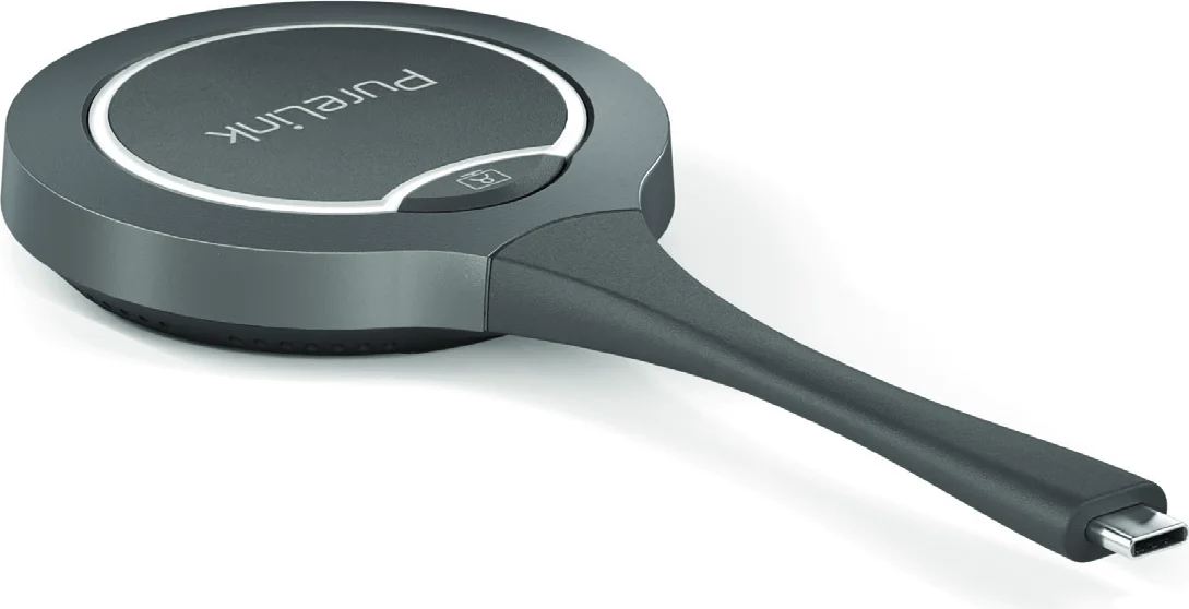
A Dongle enables users to share laptop’s content on a display wirelessly without even installing an application.
To pair a Dongle:
- Connect a Dongle to the PAIRING port of the device for pairing. Once pairing is completed, “Pairing successful” appears on the display screen.
- Connect the Dongle to a laptop. It will start running and connecting to the device’s soft AP. Once the Dongle connects to the device successfully, the Dongle LED stops blinking and starts lighting constantly.
- Now press the Dongle’s projecting button, you can share your laptop’s screen on the display immediately. Press and hold the button for at least 5 seconds, you will have your laptop’s screen displayed in full screen.
Note: For more information about the Dongle, see its user guide.
Wireless Conference
Wireless Conference function enables a laptop to access the USB conference peripherals (such as a USB camera, a USB speakerphone, etc.) attached to the switcher wirelessly through a Dongle.
Here is how to use this feature:
- Pair between the device with the Dongle. Connect the Dongle to the PAIRING port to pair two devices. Once pairing is complete, remove the Dongle from the switcher.
- Insert the dongle into the laptop. A pop-up will appear in the bottom right corner of the desktop. Click it, and in the next pop-up, select “Run PureLink-Share-Setup.vbs” to install the application.
- The installation process will run in the background and the application will start automatically after the installation is successful.
- Connect the Dongle to the laptop’s USB-C port. The Dongle will be ready to transmit and receive signals in a few seconds. Note: Please make sure the USB-C port of the laptop supports audio and video output.
- Press the Wireless Conference button on the Dongle to connect between the laptop and the USB devices wirelessly. Now you can access the USB camera and the USB speakerphone through the laptop as you wish
Multi-View
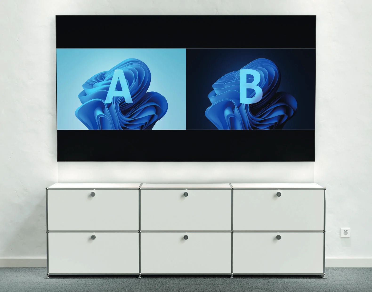
By default, the switcher allows up to two video sources to be displayed on a single screen.
Note: By default, Multi-View function is enabled and can be disabled through web UI (“Video Switching” section) and API commands. For more information about the API commands, see the separate API documentation.
Network Mode Configuration
The device equips two Ethernet ports for networking flexibility and security, which support the following two network modes:
- Transparent Mode (Default Setting) In this mode, two Ethernet ports are interconnected with each other, and each one can be used for device control by connecting to the LAN where the controller resides, for BYOD communication, and for the attached device (e.g. room PC) to access network.
- Isolated Mode When the configuration item “Secure Ethernet Mode” on web UI is set to Enable, Isolated Mode is activated. For more information about enabling “Secure Ethernet Mode”, refer to Wired Network section. In Isolated Mode, the SECURE LAN port is used for controlling the device; the UTILITY LAN port is for BYOD communication and for the attached device to access network.
Automatic Switching
The device supports automatic switching of input signals and display layouts. The automatic signal switching allows you to easily and quickly select desired sources, which follows the Last-In-First-Out rule as below:
- When one video source is connected to the device, the device will automatically output this video source to the display screen.
- When the video source being displayed is removed from the device, the device will automatically stop outputting this source to the display screen.
When the Multi-View feature is enabled, the automatic layout switching is effective,
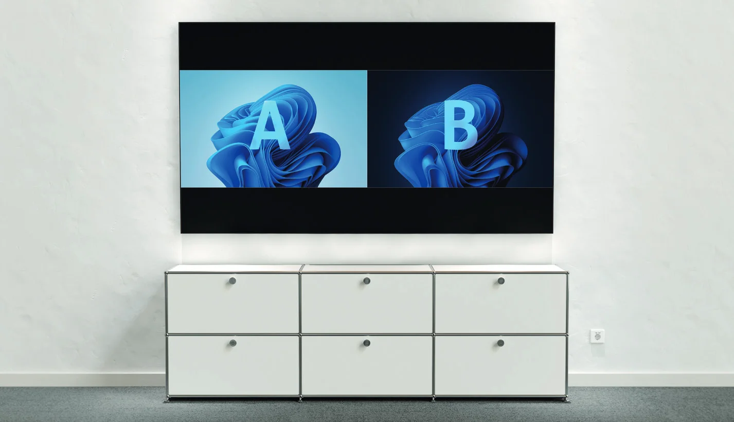
and the device will automatically select the appropriate layout to display multiple video sources simultaneously:
- When a video source is being displayed in full screen, connect one more video source to the device, the device will automatically switch to the Dual-View layout.
Key Functions
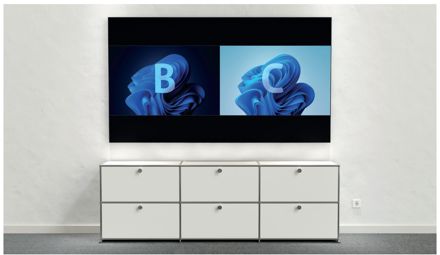
2. When two video sources are being displayed in Dual-View mode, connect an additional video source to the switcher, the latest input source will replace the source present longer on the screen.
3. When two video sources are being displayed in Dual-View, stop displaying one video source, the device will automatically switch to the full-screen Single-View layout.
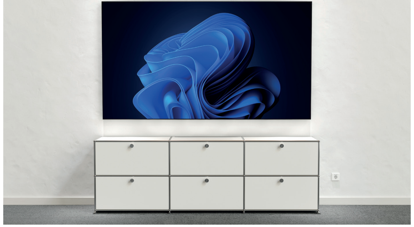
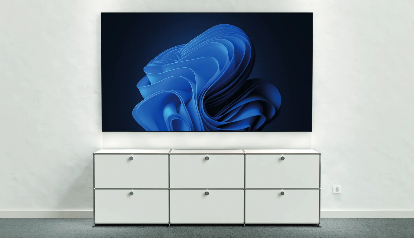
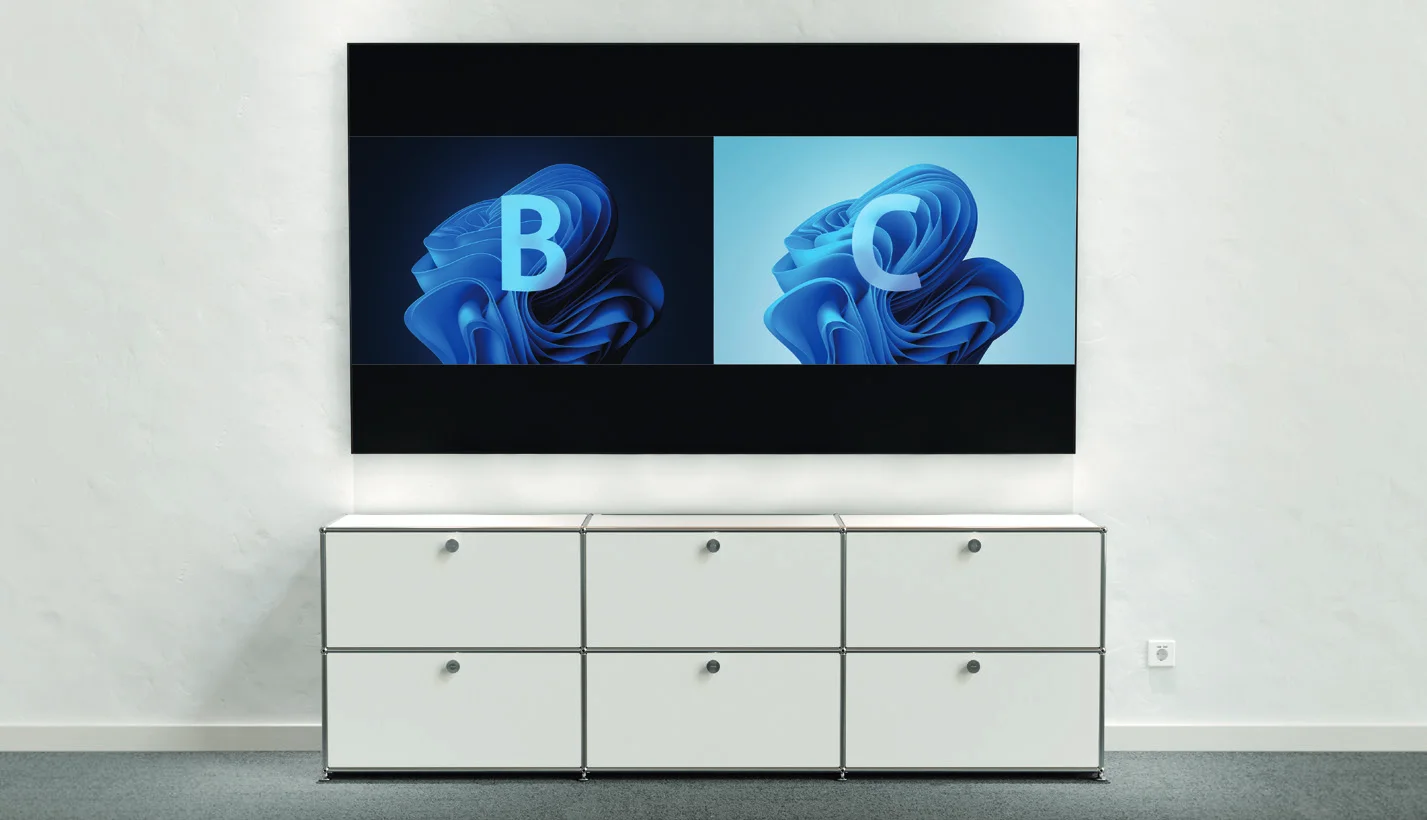
Automatic Switching function is enabled by default, if you want to enable or disable this function, please refer to the Video Switching section.
The device also provides two methods to select specific video source manually:
- Using web UI (refer to “State & Switch” section).
- Using API commands. For more information, please see the separate API documentation.
Guide Screen
The device outputs Guide Screen image when no video source is selected or being output. The Guide Screen can be personalised on the device’s Web UI page to convey customised connection instructions.
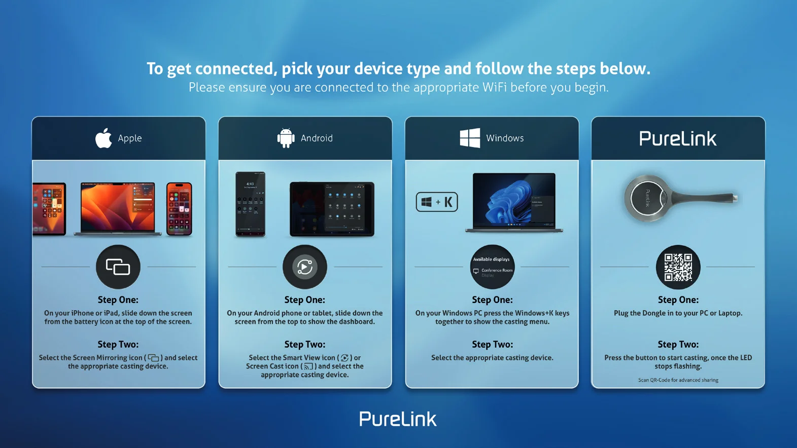
The Guide Screen is accessible in the following cases:
- Automatic switching: disconnect all video sources from the device, the Guide Screen appears automatically.
- Manual switching:
- Log on to the web UI page to select Guide Screen for the HDMI outputs. For more information see the State & Switch section.
- Send API command through telnet to the device to show the Guide Screen. For more information see the separate API documentation.
Tip: This Guide Screen image can be changed though Web UI, for more information refer to System Settings section.
By default, if the device is outputting Guide Screen for 60 seconds, a 60-second OSD countdown will appear on the Guide Screen. When the countdown reaches zero, the device will enter standby status.
OSD
The device comes with OSD (On-Screen Display) support, enables users to view basic information of the device, including video source channel, access code, device name and IP address, etc. Here are two different OSD examples:
Example 1: Full screen mode
- IP Address of the switcher
- WiFi Password of the switcher
- Device Name of the switcher
- Access Code of the switcher
- Video Source Name
Example 2: Dual-View Mode
Note: When the device outputs Guide Screen image, the OSD is shown all the time.
When the device outputs specific video sources, the OSD will display on the display device for 10 seconds and then disappear.
By default, the access code is set as blank, therefore the OSD doesn’t display the access code. If you want to set access code, please see BYOD > Access Code section for more information.
- IP Address of the switcher
- WiFi Password of the switcher
- Video Source Name
- Video Source Name
- Device Name of the switcher
- Access Code of the switcher
- Video Source Name
Web UI
The Web UI is an intuitive software interface for users to manage and control the device with ease, which can be accessed through a web browser, e.g. Chrome, Safari, Firefox, Microsoft Edge, etc. To access the Web UI:
- Connect the SECURE LAN port (or the UTILITY LAN port in Transparent Network mode) of the device to a local area network. Tip: Ensure there’s a DHCP server in the network so that the device can obtain a valid IP address.
- Connect the PC to the same network as the device.
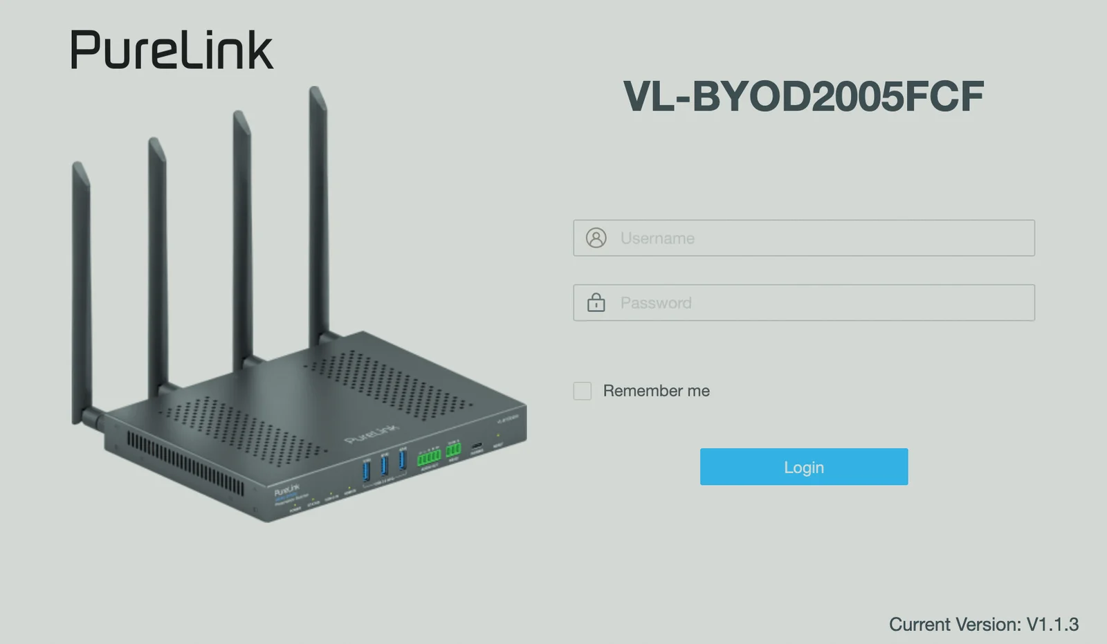
- Input the device’s IP address in the browser and press Enter, the following window pops up. Default settings (without DHCP): IP: 169.254.1.102
- Subnbet: 255.255.0.0
- Gateway: 169.254.0.1
- Input the password and click Login. Default user: admin Default password: admin
Tip: For the first login, you need to set up a new login password in the following dialog box and Save and Continue to enter the main page. The new password must be alphanumeric only with 4 to 16 characters in length.
The main page comprises of the General, Video Source and Display pages.
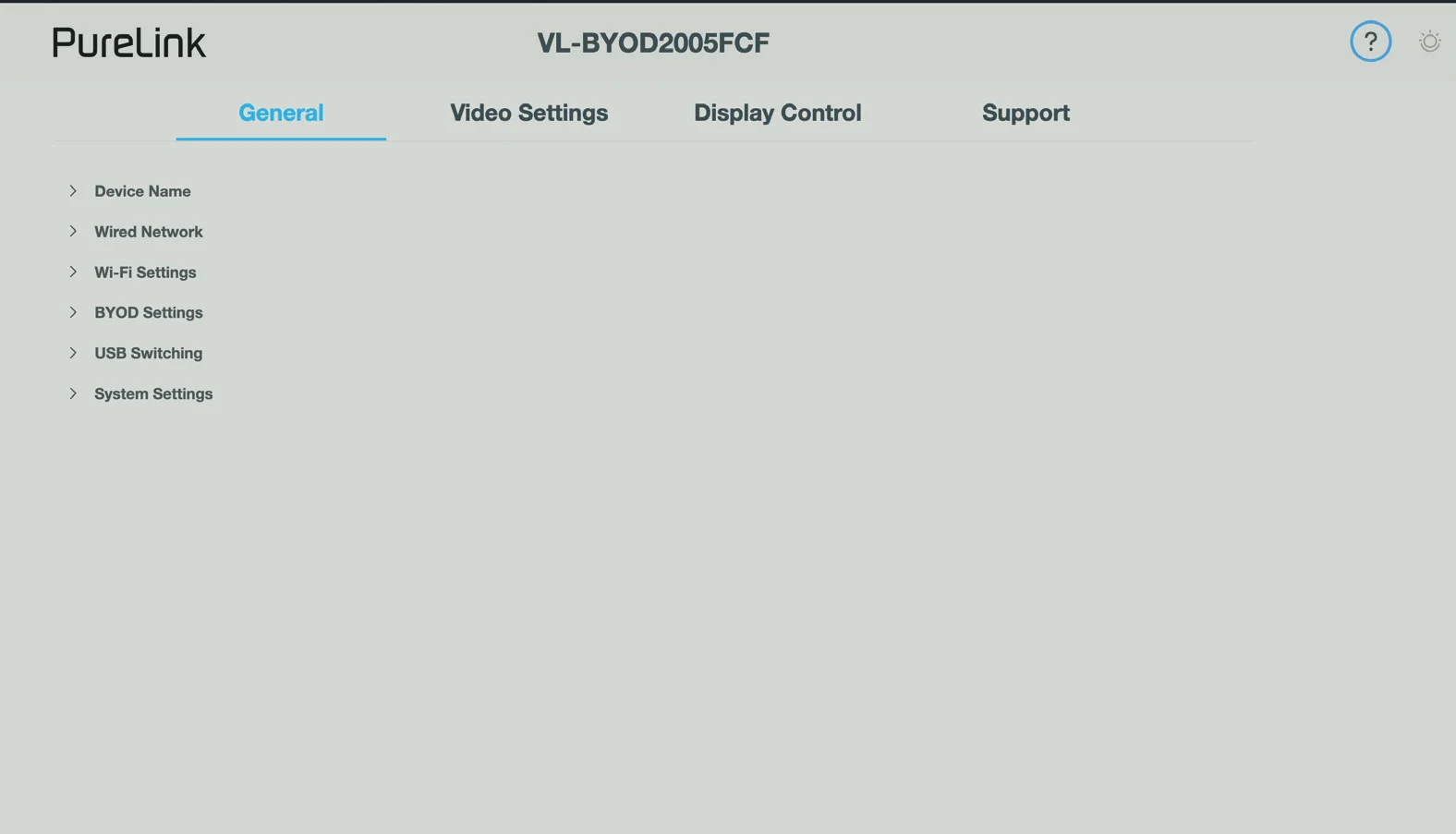
General Tab
Device Name
Device Name Define the device name to an easy to remember one.
Name
Note: The device name must be 1~20 characters in length, including letters, numbers, “_” or “-”.
The device name is also used as the identifier for BYOD screen casting methods, including Airplay, Miracast and Dongle, and its uniqueness must be guaranteed. When multiple devices are deployed in the environment, make sure that all devices’ names are different.
Default setting: BYOD200
Apply Click to perform current settings.

Wired Network
Primary (SECURE LAN) Port:
- IP Mode Select IP addressing mode between DHCP and Static. Default setting: DHCP
- IP Address Set IP address manually for the device when Static Mode is selected.
- Netmask Set subnet mask manually for the device when Static Mode is selected.
- Gateway Set gateway address manually for the device to communicates with another network when Static Mode is selected.
- DNS Server 1 & 2 Set DNS server manually for the device to ensure normal network communication.
- Apply Click to save and perform current settings.
Note: After the IP settings are changed, please refresh the Web UI page to log back in.
Secure Ethernet Mode:
- Secure Ethernet Mode To enable or disable the Secure Ethernet Mode
- Enable: Select to activate Isolated mode. In Isolated mode, the SECURE LAN port is used to control this device, the UTILITY LAN port is used for BYOD communication and network access.
- Disable: Select to activate transparent mode. In Transparent mode, two Ethernet ports are interconnected with each other. Default setting: Disable
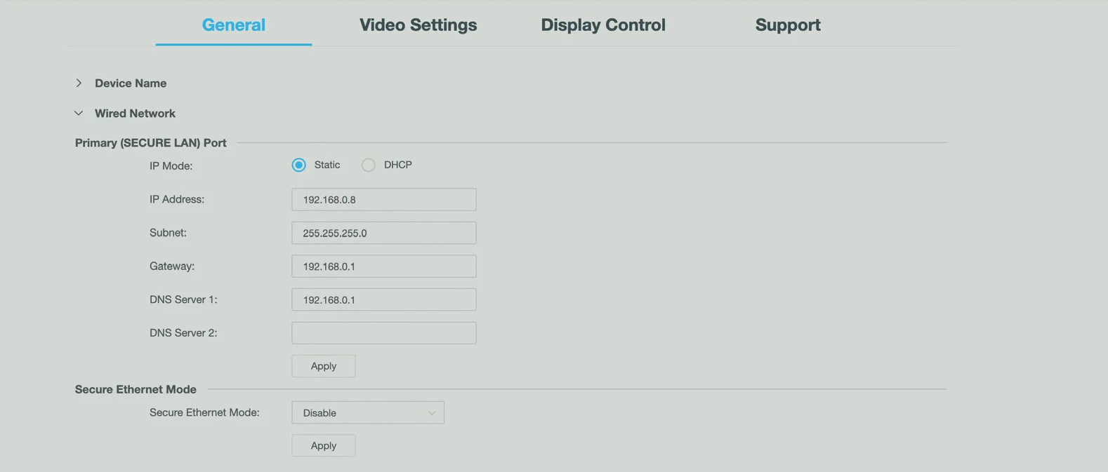
Note: For more information about the two network modes above, refer to Network Mode Configuration section.
Wi-Fi Settings
- Band
- 5G: Configure the device’s frequency band as 5GHz.
- 2.4G: Configure the device’s frequency band as 2.4GHz. Default setting: 5G
Tip: If your wireless devices don’t support 5GHz Wi-Fi, configure the frequency band of this device as 2.4G before connecting them to this device via Miracast.
- Channel Configure the device’s wireless channel. Default setting: Auto. Auto means the device selects a wireless channel automatically for itself.
- Soft AP Click to enable/disable the device’s soft AP function. Default setting: Enable.
Note: Ensure that the soft AP function is enabled before using Dongle and wireless screen casting features.
- Soft AP Password Configure the soft AP password. Default setting: 12345678
- Soft AP Router
- Enable: Enable the device’s soft AP router function so that wireless devices connected to soft AP are able to access the internet (verify the Ethernet port of the device is connected to the internet).
- Disable: Disable the device’s soft AP function to prevent wireless devices connected to soft AP from accessing the internet. Default setting: Enable.
Note: When the device’s IP mode is set as Static, you must configure the Ethernet port’s gateway and DNS correctly so that soft AP router runs properly.
Note: Ensure that the soft AP function is enabled before using Soft AP Router feature.
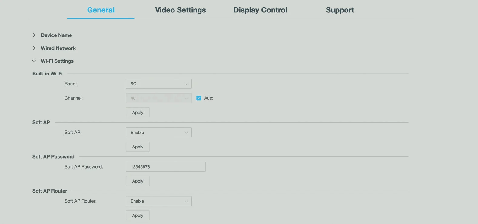
Apply Click to save and perform current settings.
BYOD Settings
- BYOD Feature Select to enable/disable the device’s BYOD feature. Default setting: Enable.
Note: This feature is available for Airplay and Miracast, not for Dongle.
- Access Code Enter a four-digit access code to help prevent users from accidentally connecting to an unintended device and protect from unauthorised access.
- When an access code is set, it will appear on the upper right corner of the attached display.
- If you don’t want to set access code, you can leave it blank here. Default setting: Null.
Note: Access Code works for Airplay and Miracast (MS-MICE disabled) only.
- MS-MICE Feature Select to enable/disable the device’s MS-MICE Feature.
- MS-MICE refers to the Miracast over Infrastructure Connection Establishment protocol, which is developed by Microsoft and perceived as the upgraded version of Miracast, can transmit Miracast stream over the infrastructure network (existing LAN or WLAN).
- Enable: Windows will only select infrastructure network when connection between Miracast source and Miracast receiver is through Ethernet or a secure Wi-Fi network; if not, Windows will retrieve to use Miracast P2P instead of MS-MICE.
- Disable: Windows selects Miracast to wirelessly send screencasts based on the Wi-Fi peer-to-peer (P2P) connection. Default setting: Disable
Note: When MS-MICE is working, Access Code is not available.
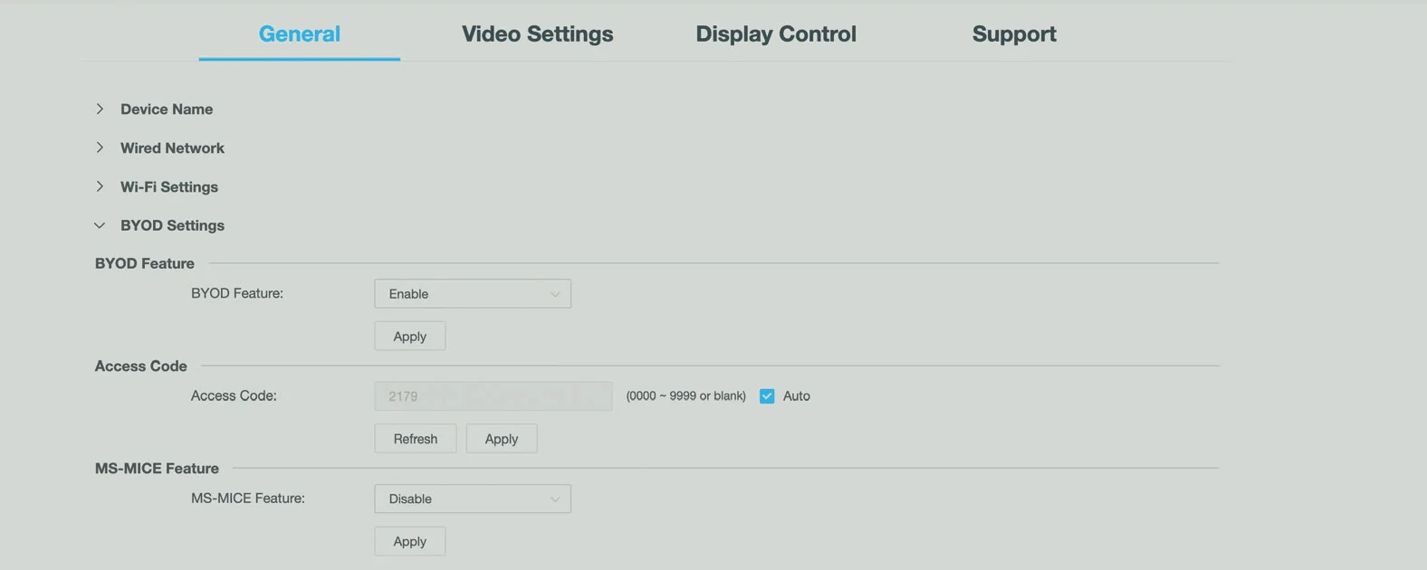
Apply Click to perform current settings.
System Settings
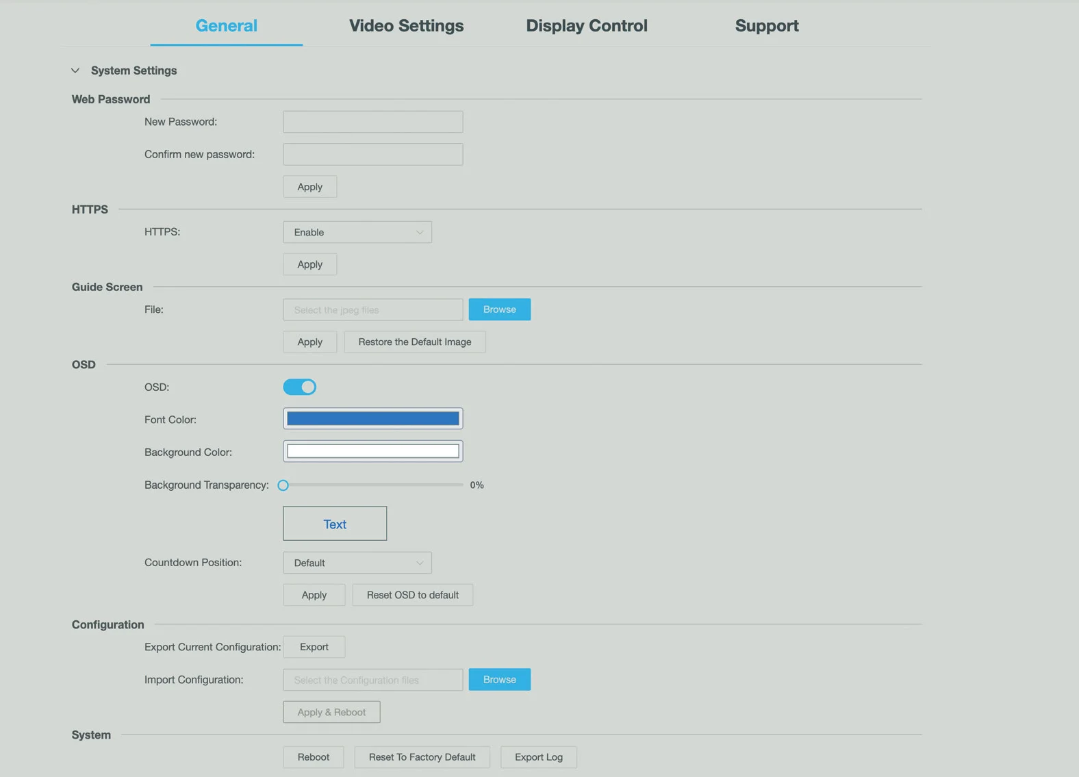
Web Password
- New Password/Confirm new Password: Set a new password to log on to the device’s web UI page.
- Apply: Click to apply settings.
Note: The new password must be 4 to 16 characters in length, alphanumeric only
HTTPS
- HTTPS: Click the drop-down list to toggle the HTTPS feature
- APPLY: Click to apply settings
Guide Screen
- Browse: Click to browse for the new Guide Screen image.
- Apply: Click to upload the selected image to the device.
Note: Image in jp(e)g format with 1920x1080 pixels is recommended.
OSD
- OSD: Click to goggle the OSD feature
- Font Color: Change the OSD text color
- Background Color: Change the OSD background color
- Background Transparency: Change the transparency of OSD overlaying the video
- Text: Preview of the OSD with the above configurations
- Countdown Position: Change the position where to show the standby countdown
- Apply: Click to apply settings
- Reset OSD to default: Click to restore default OSD settings
System
- Reboot: Click to reboot the device.
- Reset to Factory Default: Click to restore the device to factory defaults. You can also perform this task by pressing and holding the Reset button on front panel for five seconds.
- Export Log: Click to export system log.
Apply Click to perform current settings.
Video Settings Tab
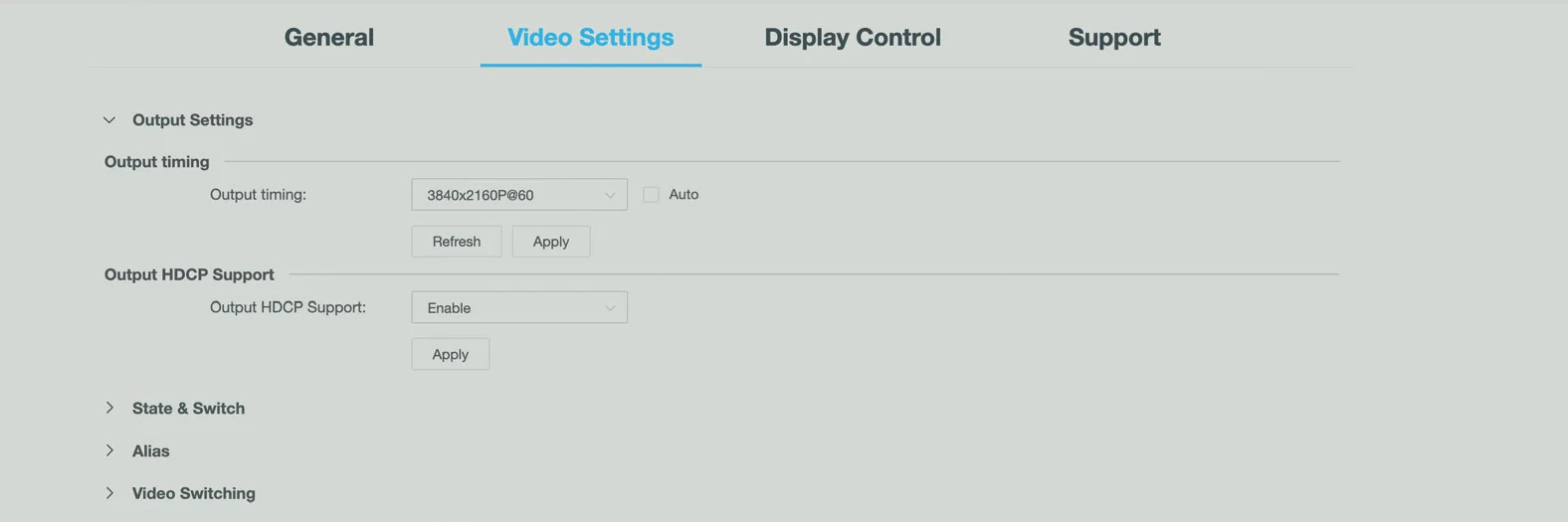
Output Settings
- Output timing Set the output timing for the video received. Two operation methods are offered in the following:
- Auto: Select to output the optimal resolution of the attached display based on the display’s EDID. For example, if the recommended resolution for the display is 4K 60Hz, the device will output 4K 60Hz video.
- Resolution range list: select a desired output resolution from the dropdown menu to output this fixed resolution. Maximum supported output resolution is 4K 60Hz. Default setting: Auto
- Output HDCP Support Select to enable or disable HDCP support of the output port. Two options are offered in the following:
- Enable: To enable HDCP support of the output port. In this case, the HDCP setting of the output port will follow that of the connected display. This option is applicable to HDCP-enabled displays.
- Disable: To disable HDCP support of the output port. Default setting: Enable
Apply Click to perform current settings.
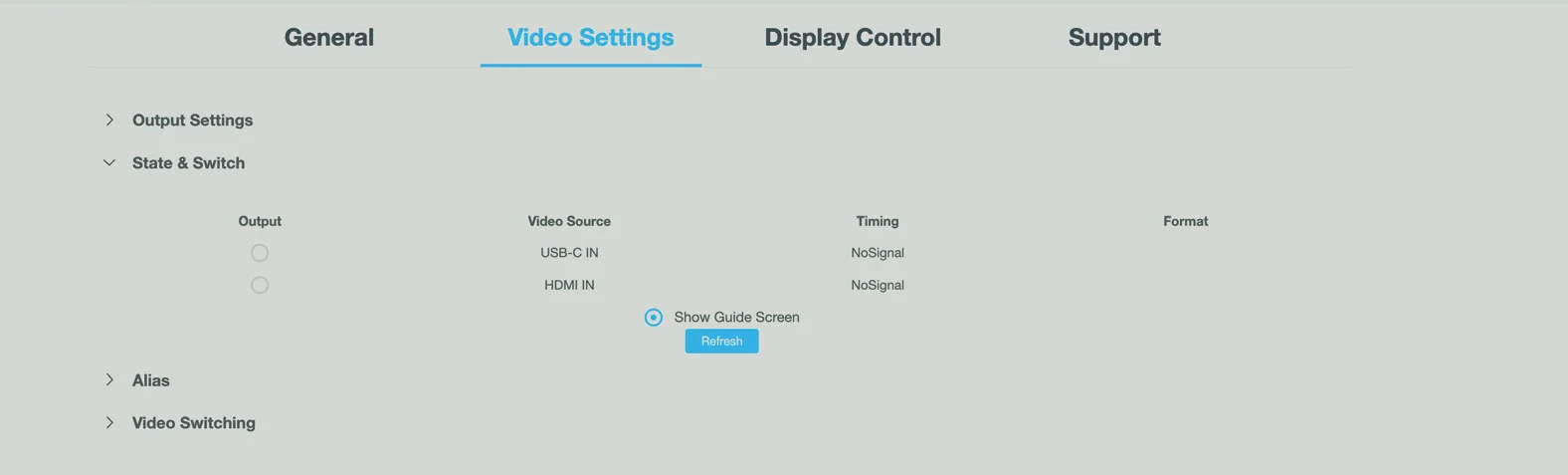
State & Switch
This section is used for switching among multiple input sources and displaying the sources’ statuses, including video source names, input resolutions and format.
Output
Click the button to select (button turns from white to blue) or deselect (button turns from blue to white) the specified video source for HDMI OUT.
Show Guide Screen
Click the button to output the Guide Screen (button turns from white to blue).
Refresh
Click to refresh the current state information.
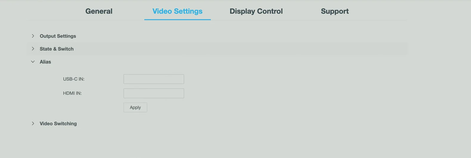
Alias
Alias
Enter a new alias name to change the video source name to a new one.
Note: The alias name must be within the length of 1~20 characters, including alphanumeric characters, underscores “_” and hyphens “-”, but shall not start with “-” or be pure numbers. If you don’t want to change the name, leave it blank here.
Apply
Click to perform the current settings.
Video Switching
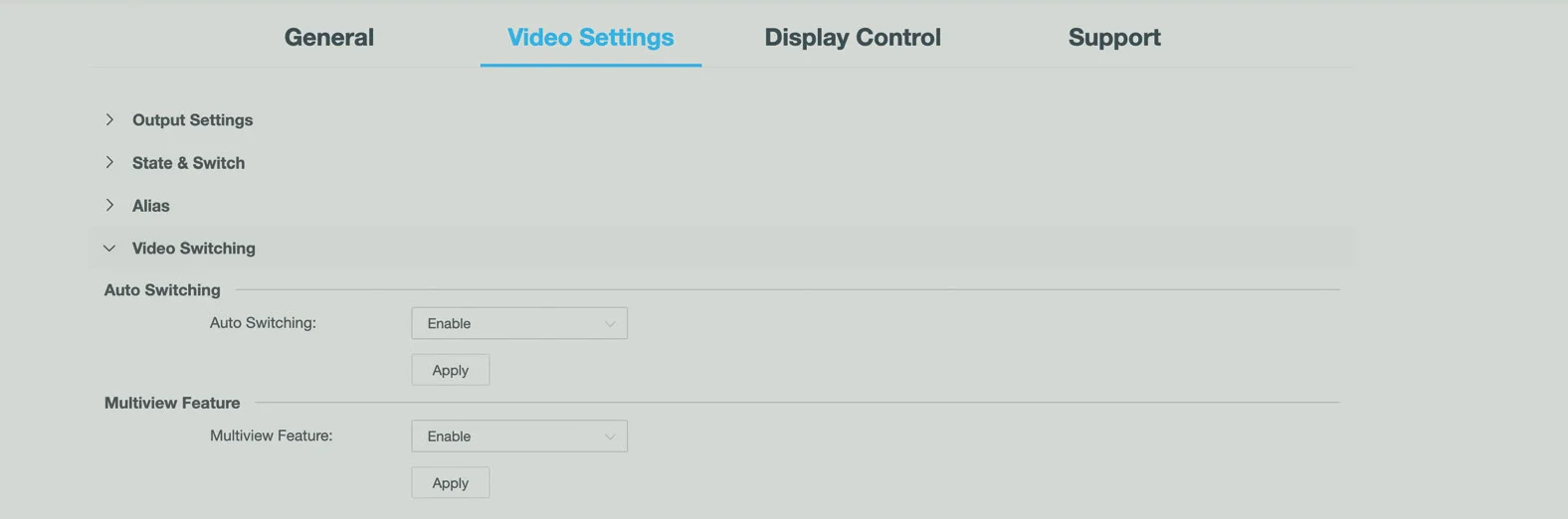
Auto Switching
- Enable: Enable the Auto Switching function.
- Disable: Disable the Auto Switching function.
Default setting: Enable
Note: For more information about Auto Switching function, please refer to Automatic Switching function.
Multi-View Feature
- Enable: Enable the Multi-View Feature.
- Disable: Disable the Multi-View Feature.
Default setting: Enable
Display Control
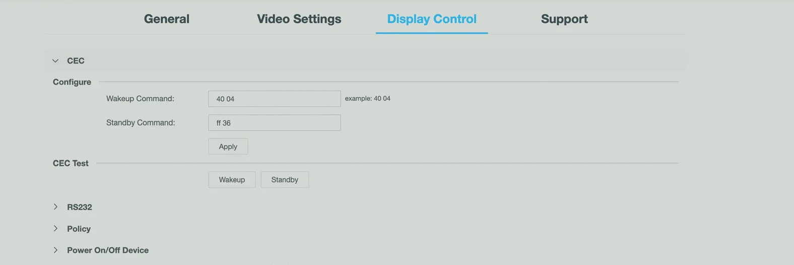
CEC
Wake up Command
Enter the CEC wake up command of the controlled display device in hex format. For more information about the command, see the user guide of your display device.
Default setting: 40 04
Standby Command
Enter the CEC standby command of the controlled display device in hex format. For more information about the command, see the user guide of your display device.
Default setting: ff 36
Apply
Click to save and perform current settings.
Wake up
Click to send the Wakeup command to wake the display up from standby mode (for testing).
Standby
Click to send the Standby command to make the display enter standby mode (for testing).
RS232
| Parameter | Value | Abbreviation |
|---|---|---|
| Baud Rate | 115200bps | 115200 |
| Data Bits | 8bits | 8 |
| Parity | None | n |
| Stop Bits | 1 | 1 |
RS232
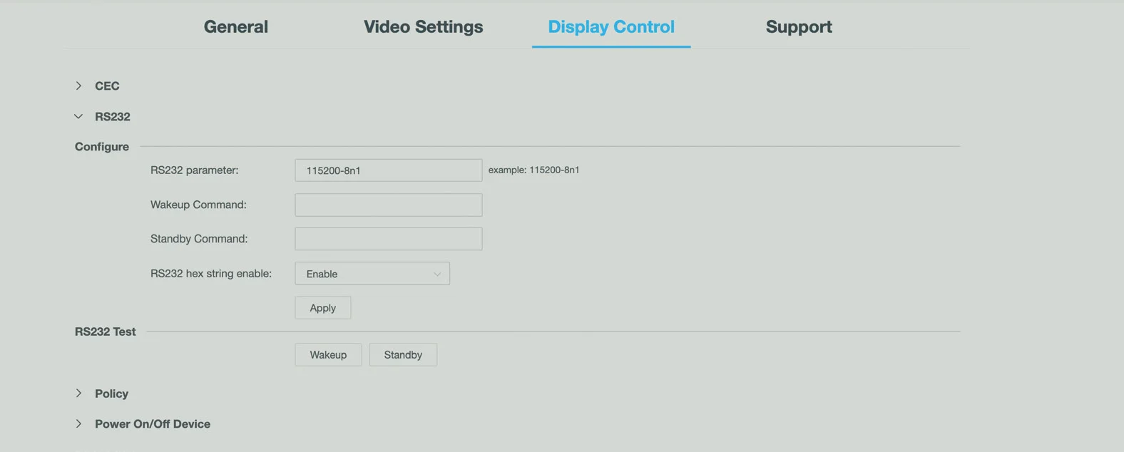
RS232 Parameter
Set the RS232 parameters for the controlled display. For more information about the parameters, see the user guide of your display device.
Wakeup Command
Enter the RS232 wakeup command of the controlled display device. For more information about the command, see the user guide of your display device. If you want to disable this function, you can enter nothing here.
Default setting: blank
Standby Command
Enter the RS232 standby command of a controlled display device. For more information about the command, see the user guide of your display device. If you want to disable this function, you can enter nothing here.
Default setting: blank
RS232 hex string enable
- Enable: select to use the RS232 standby and Wakeup Commands in hex string form to control your display devices. If this item is enabled, make sure Standby and Wakeup Commands are manually converted to their equivalent hex forms first and then input the RS232 Standby Command and RS232 Wakeup Command. For example, RS232 Wakeup Commands in hex form may be: 50 57 52 20 4F 4E 0D 0A
- Disable: select to directly send the original Standby or Wakeup Commands to control the attached display device.
Default setting: Enable
Apply
Click to perform current settings.
Wakeup
Click to send the Wakeup Command defined in “Wakeup Command” field to wake the display up from Standby Mode.
Standby
Click to send the Standby Command defined in “Standby Command” field to set the display to enter Standby Mode.
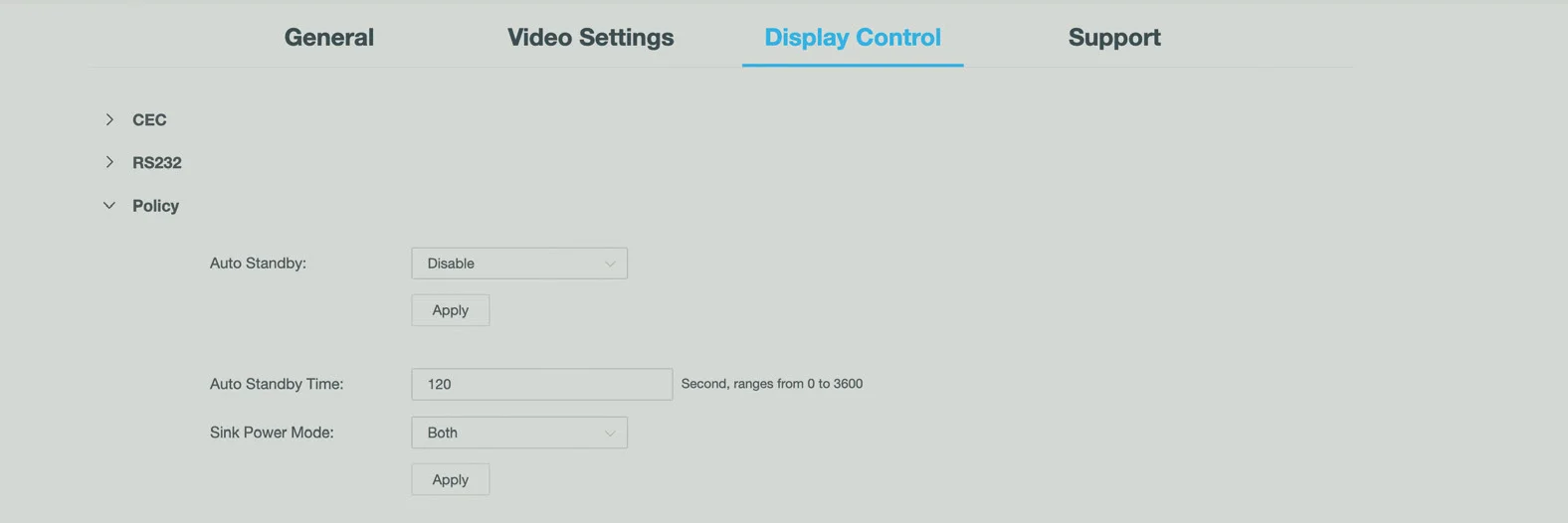
Policy
Auto Standby
- Enable: To enable auto standby function for the device. If enabled, when there’s no valid signal input to the device during a specified period of time, the device will enter standby status automatically.
- Disable: To disable auto standby function for the device.
Default setting: Enable
Auto Standby Time (Second, ranges from 0 to 3600)
Set the Standby Timeout (inactivity period) after which the device will automatically enter the Standby Mode.
- If the Standby Timeout doesn’t exceed 60 seconds, a standby countdown of the device will appear on the display screen immediately once it outputs Guide Screen.
- If the Standby Timeout is larger than 60 seconds, a 60-second Standby countdown of the device will appear on the display screen when the Standby Timeout has only 60 seconds left.
- If Auto Standby Time is set to 0, it means the device will enter Standby Mode immediately once it outputs Guide Screen.
For example, an 80-second auto Standby Time means the device will enter Standby Mode after it has not detected valid signal input for 80 seconds, during which when the device has output Guide Screen for 20 seconds, a 60-second countdown appears on the display, as the countdown reaches zero, the device enters Standby Mode.
Default setting: 120
Sink Power Mode
- Both: Enable both CEC and RS232 modes to manage the sink power.
- CEC: Enable CEC to manage the sink power.
Default setting: Both
Apply
Click to save and perform current settings
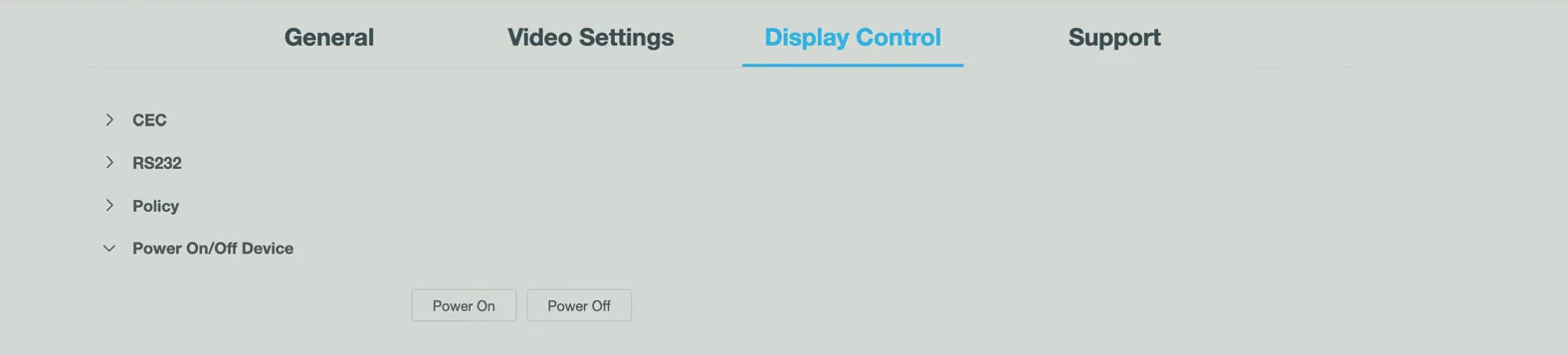
Power On/Off Device
Power On Click to wake the device up from the Standby Mode.
Power Off Click to set the device to Standby Mode.
Support Tab
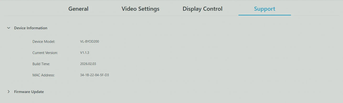
Version Info
Version Shows the device’s firmware version.
Build Time Shows the time and date when the device’s firmware was built.
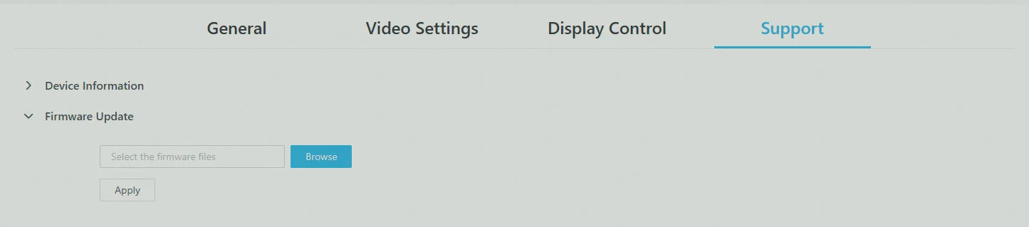
Firmware Update
Firmware UpdateBrowse: Click to browse for the local upgrade file.Apply: Click to upload the firmware file to the device and perform firmware upgradeNote: The legal firmware package is a .zip archive. The device reboots after firmware update is complete.
Warranty and liability
If any fault or damage is detected on your product, please contact your dealer and provide your sales slip or invoice as evidence of the purchase, if necessary. Your dealer will repair the fault either on site or send the device to the manufacturer. Please describe all faults in detail especially intermittent faults which may not be obvious at first inspection. Only with complete information can we be sure to repair all faults in full.
Disclaimer of liability
We as the manufacturer will not be held liable, nor provide any warranty for damage resulting from improper installation, assembly and use of the product, or failure to observe the operating instructions and/or safety instructions.
Trademark
Product model and logo are trademarks. All other trademarks mentioned in this manual are acknowledged as the property of the trademark owners. No part of this publication may be copied or reproduced without prior written permission of their respective owners.
CE Conformity
PureLink GmbH hereby declares that this product is in compliance with the essential requirements and other relevant provisions of the RED Directive 2014/53/EU and the RoHS Directive 2011/65/EU amended by 2015/863/ EU. PureLink GmbH hereby declares that this product is in compliance with the essential requirements of the Electromagnetic Compatibility Regulations 2016 and all other applicable UK regulations.
The EU Declaration of Conformity is available here: www.purelink.de
Disposal of device
Disposal of the Device
WEEE-Reg. No.: 93847290
According to the European WEEE Directive, electrical and electronic equipment may not be disposed of with household waste. As a consumer, you are obliged to return electrical and electronic equipment free of charge at the end of its service life to the public collection points set up for this purpose or to the point of sale. Details on this are regulated by the respective national law. The symbol on the product, the instructions for use or the packaging refers to these regulations. Recycling old appliances in this way is an important contribution to the protection of our environment.
Legal & Compliance
Product identification
Model: VL-BYOD200 – manual version 1.0
WEEE reg. no.: DE 93847290
Packaging
Dispose of packaging separately by material (paper/cardboard, plastics) via the local collection systems. Keep packaging material away from children – risk of suffocation. Packaging register LUCID: DE5958616449295.