
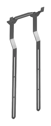
General Notes
Safety Instructions
Usage
Only use the product for the intended use case described in this user manual.
Maintenance
Regularly clean the product with a soft, dry cloth to maintain the correct function.
Do not attempt to disassemble or repair the product yourself. Contact customer support for any issues.
Children and Pets
Keep the products, the accessories and the packaging out of reach of children and pets to prevent accidental injury or damage.
Authorized Service
Only authorized personnel should perform repairs or modifications to the product. Contact customer support for assistance.
Storage
When not in use, store the product in a cool, dry place away from direct sunlight and extreme temperatures.
Delivery Contents
- 1x VL-VB-MNT100
- 1x Screw set
- 1X Manual
1. Unboxing
Post-delivery, check the contents of the package, has the delivered VB-MNT100 arrived undamaged, does it have visible dents or scratches.
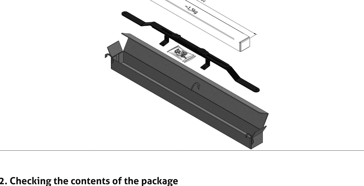
2. Checking the contents of the package
The package should contain:
- Handle body – 1 piece
- Handle arms – 2 pieces
- Bag with the following contents:
- Allen key 4mm – 1 piece
- Allen screw with countersunk head M6x16 – 2 pieces
- Allen screw cap 4mm – 2 pieces
- Plastic washer 20x8.4x2.5mm – 2 pieces
- Plastic washer 20x6.3x2.5mm – 2 pieces
- Aluminum washer 25x8.5x4mm – 2 pieces
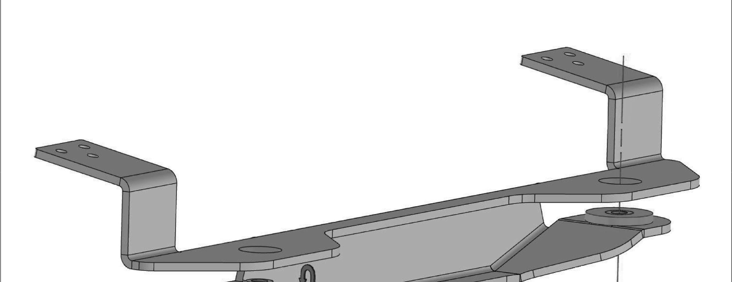
3. Installation of washers on threaded sleeves
Insert two plastic washers 20x8.4x2.5mm into the handle body. The washers should be placed on the threaded sleeves made inside the body.
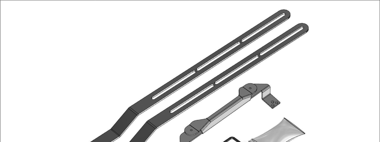
4. Insert the arms into the body
Insert the arms into the body so that the 6.5mm holes in the arms match the 8.4 mm holes in the previously inserted washers. Depending on the intended use, the arms can be mounted with the bend facing up or down.
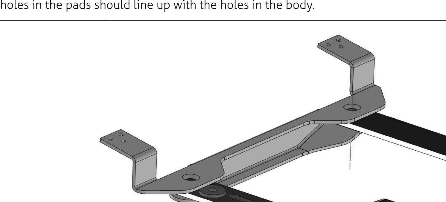
5. Insert the pressure pads into the body
Place pressure pads 20x6.3x2.5mm on the arms and slide them into the body. The holes in the pads should line up with the holes in the body.
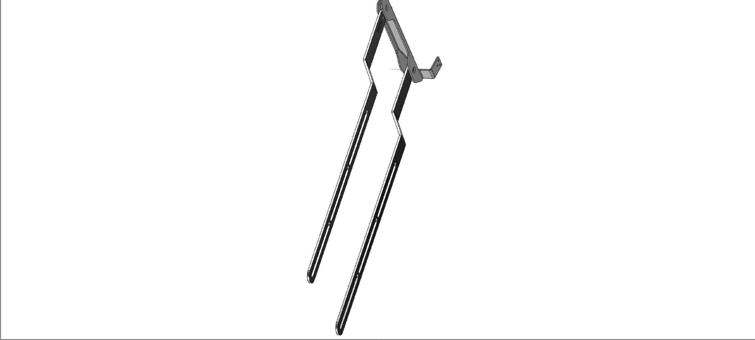
6. Screwing the arms to the body
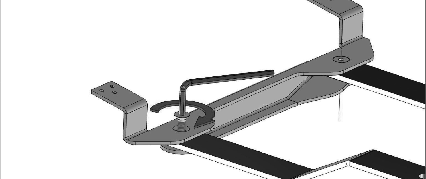
Sets consisting of two washers and an arm are screwed to the body using a conical M6x16 screw. To tighten the screw, use the 4mm Allen key included in the set.
Tighten the screws firmly so that the arms move hard inside the body - with clear resistance.
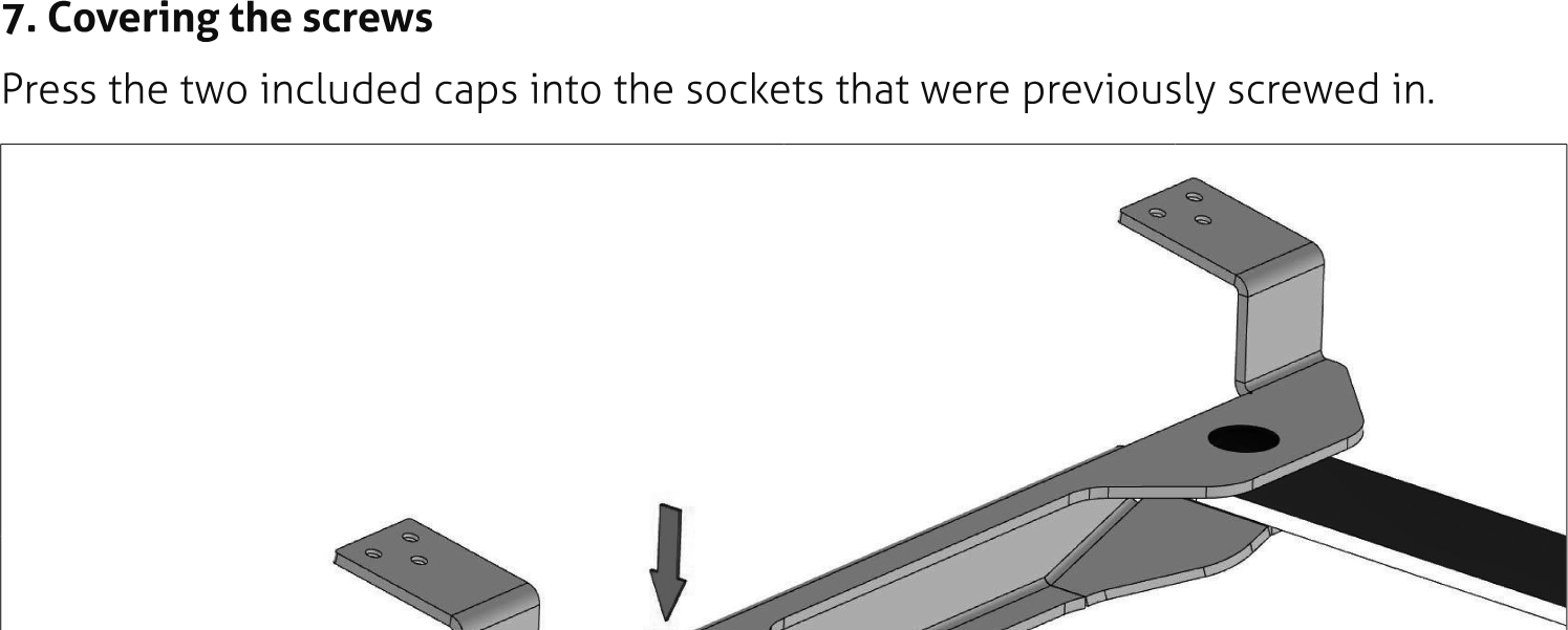
7. Covering the screws
Press the two included caps into the sockets that were previously screwed in.
8. Screwing the mount to the Video Bar
Use the six screws included in the kit to attach the mount to the video bar.
9. Setting the mount arms according to the monitor's VESA holes
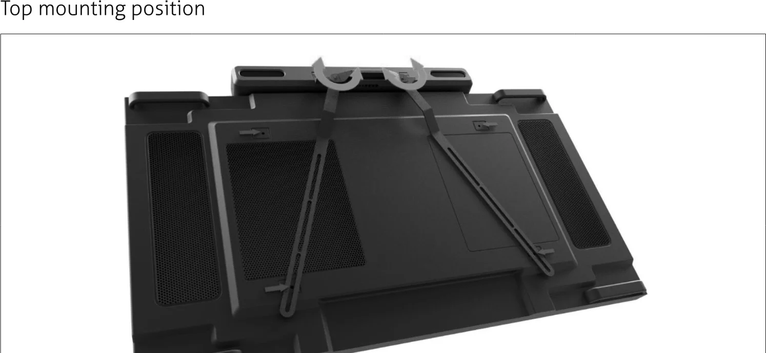
Place the monitor face down on a soft and even surface. Place the arms of the VB-MNT100 mount with the PureLink VL-VB300 videobar screwed on the back of the monitor. Fold the arms of the mount so that they align with the two upper or lower VESA holes of the monitor.
Depending on the desired installation position, the videobar can be placed on the top or bottom of the monitor
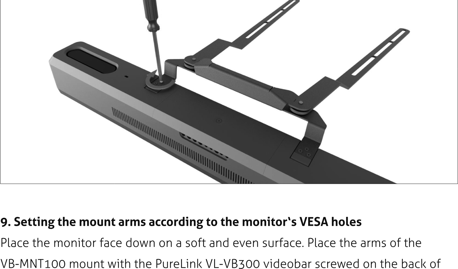
It should be noted that the VB-MNT100 mount is designed to work with monitors from 43" to 98" and with VESA hole spacing from 300x300 to 800x400.
Top mounting position
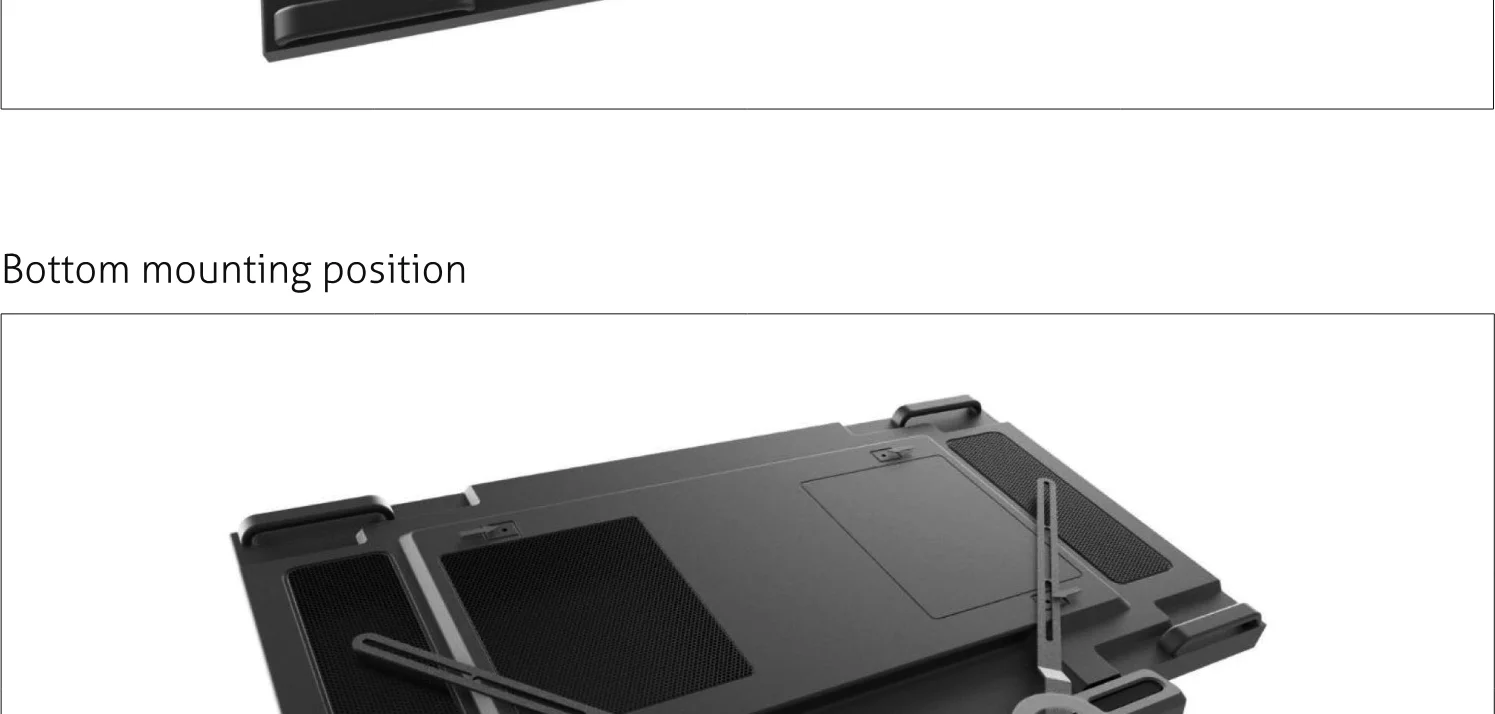
Bottom mounting position
10. Spacers placement
Place two 25x8.5x4mm spacers on the monitor’s VESA holes that do not align with the arms of the VL-VB-MNT100 mount.
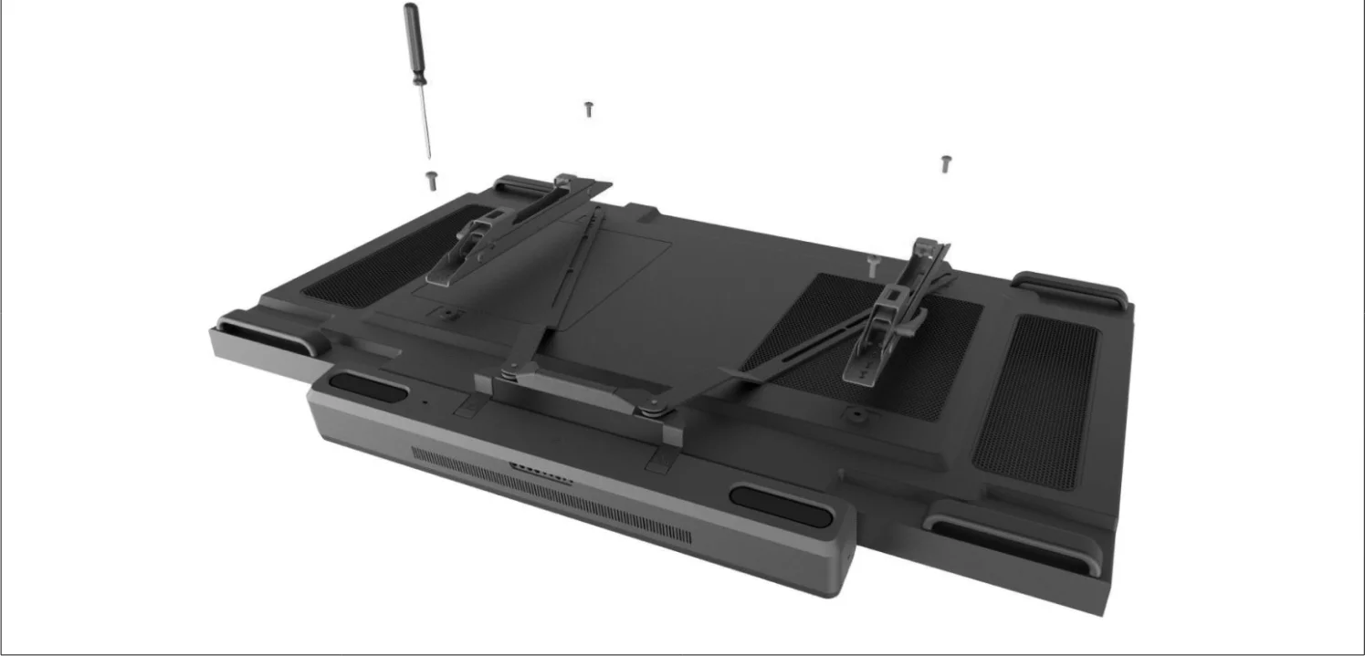
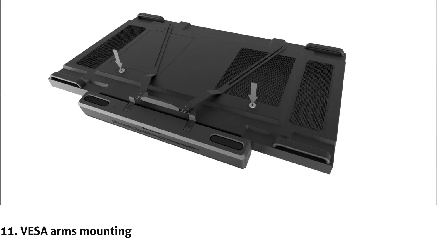
11. VESA arms mounting
Screw the VESA arms to the monitor with the VL-VB-MNT100 mounting arms set.
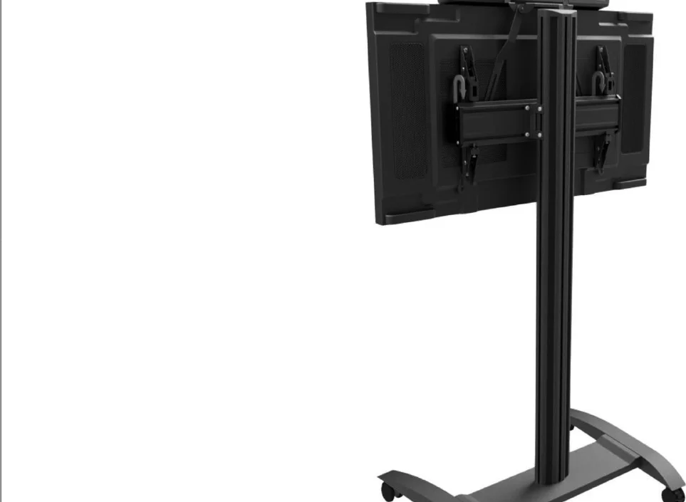
12. Hanging the screen on the wall mount or TV trolley
Hang the monitor with the Video Bar and arms mounted on the holder on the wall mount or TV trolley.
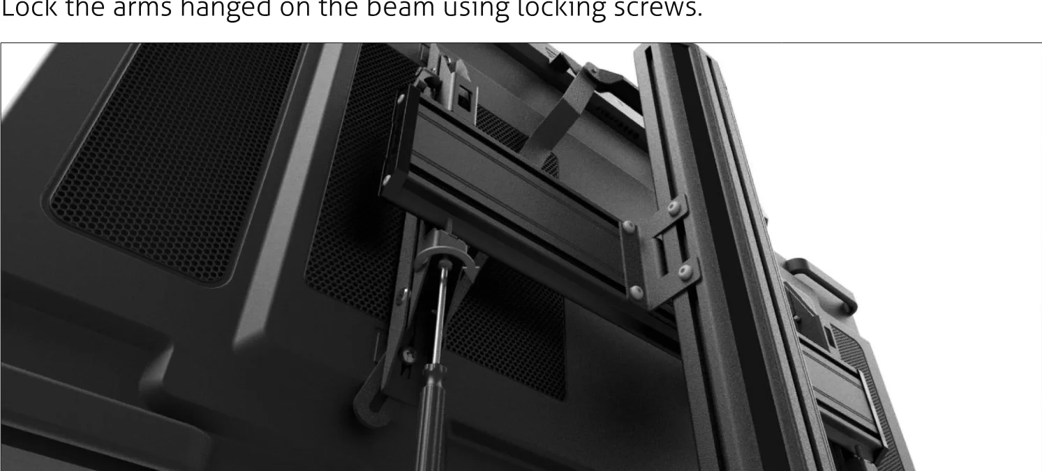
13. Locking the arm on the beam
Lock the arms hanged on the beam using locking screws.
Warranty and liability
If any fault or damage is detected on your product, please contact your dealer and provide your sales slip or invoice as evidence of the purchase, if necessary. Your dealer will repair the fault either on site or send the device to the manufacturer. Please describe all faults in detail especially intermittent faults which may not be obvious at first inspection. Only with complete information can we be sure to repair all faults in full.
Disclaimer of liability
We as the manufacturer will not be held liable, nor provide any warranty for damage resulting from improper installation, assembly and use of the product, or failure to observe the operating instructions and/or safety instructions.
Trademark
Product model and logo are trademarks. All other trademarks mentioned in this manual are acknowledged as the property of the trademark owners. No part of this publication may be copied or reproduced without prior written permission of their respective owners.
PURELINK GMBH
Von-Liebig-Str. 10
D - 48432 Rheine
Germany
www.purelink.de
V1 | September 2024
Legal & Compliance
Product identification
Models: VL-VB-MNT100, VL-VB300-SET01 – manual version 1.0
Disposal of electrical and electronic equipment
Applies to: VL-VB300-SET01
Only for products marked with the crossed-out wheelie bin on the product or packaging.
WEEE reg. no.: DE 93847290
The crossed-out wheelie bin symbol on the product, packaging or in this manual means that electrical and electronic equipment must not be disposed of with household waste at the end of its life. Hand in old devices free of charge at a public collection point or return them to a distributor obliged to take them back. Remove batteries and lamps that can be removed without destroying the device before handing it in, and delete any personal data stored on the device. Details are regulated by national law. By returning old devices you help protect the environment.
Packaging
Dispose of packaging separately by material (paper/cardboard, plastics) via the local collection systems. Keep packaging material away from children – risk of suffocation. Packaging register LUCID: DE5958616449295.