
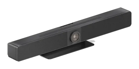
Introduction
The VL-VB300-PRO is an all-in-one collaboration solution that simplifies meetings in huddle spaces and small to medium-sized meeting rooms. Combining video conferencing, presentation sharing and wireless collaboration in a single device, it helps teams communicate and work together more effectively.
AI-powered camera technology automatically keeps speakers and presenters in focus, creating a more engaging and natural meeting experience for both in-room and remote participants. Flexible wired and wireless content sharing options make it easy to present from a range of devices, while seamless compatibility with platforms such as Microsoft Teams, Zoom and Webex ensures straightforward deployment.
With clear room-filling audio, intelligent voice enhancement and simple control options, the VL-VB300-PRO delivers a professional conferencing experience that enables productive meetings with minimal setup and maximum ease of use.
General Notes
Please read this user manual in its entirety and carefully. It forms part of the product and contains important notes for operating and storing. Please keep this document in a safe place for other users or for personal reference.
This product is intended for indoor use only. Please do not use it in any outdoor areas. Any contact with water and moisture must be avoided under all circumstances.
For product safety and compliance purposes (CE) please do not rebuild and/or modify this product. Please note that if you use the product for purposes other than those described above, the product may be damaged. In addition, improper use can cause hazards such as short circuiting, fire, electric shock, etc.
Safety Instructions
Caution: Read the operating instructions carefully and especially observe the safety information. If you do not follow the safety instructions and information on proper handling in this manual, we assume no liability for any resulting personal injury or damage to property. Such cases will invalidate the warranty/guarantee.
Electrical Safety
Caution: Ensure that the product is connected to a power source that matches the specifications provided in the user manual. Do not expose the product to water or moisture to prevent electrical shock or damage.
Mains Cable Usage
Only use the product with the supplied accessories. Do not attempt to modify or replace it.
Usage
Only use the product for the intended use case described in this user manual.
Maintenance
Regularly clean the product with a soft, dry cloth to maintain the correct function. Do not attempt to disassemble or repair the product yourself. Contact customer support for any issues.
Children and Pets
Caution: Keep the products, the accessories and the packaging out of reach of children and pets to prevent accidental injury or damage.
Unattended Operation
Do not leave the product unattended while it’s being used. Turn off/unplug the product when not in use.
Authorized Service
Only authorized personnel should perform repairs or modifications to the product. Contact customer support for assistance.
Emergency Disconnect
Caution: In case of any unusual behavior (e.g., overheating, smoke), immediately disconnect the product from the power source and contact customer support.
Storage
When not in use, store the product in a cool, dry place away from direct sunlight and extreme temperatures.
Delivery Contents
- 1x Video bar
- 1x DC 20V/6A Power Adapter
- 1x AC cable with EU pin
- 1x Remote Controller
- 1x Magnetic Lens Cap
- 1x Wall Mounting Kit
- 4x Expansion Screws
- 4x Mounting Screws
- 1x USB to RJ45 adapter cables for VL-MIC110
Features
- Smart video conference collaboration device. All-in-one solution for all meeting scenarios
- Wired screen presentation via USB-C and HDMI
- Wireless Casting and Wireless Conferencing via 4K Dongle VL-DGL200
- Wide angle 4K video camera with 120° FOV
- 8x MEMS digital microphone arrays with a range of 8 meters and an angle of 180°
- 2x 8W Stereo full range speakers with passive radiator bass enhancement
- Includes AEC (Acoustic Echo Cancellation), AGC (Automatic Gain Control), ANS
- (Automatic Noise Suppression) and full duplex mode communication to make all participants feel like they are in the same room
- Auto Framing / Speaker Tracking / Presenter Tracking / Individuals Gallery based on AI technology makes meetings more intimate and friendly
- Plug and play with excellent compatibility for OS and UC applications, e.g. Zoom, Teams, Webex, Tecent Meeting, etc.
- Provides flexible control options via Web GUI and Remote Controller
- Built-in Wi-Fi
Specifications
Video
| Input Video Port | 1x HDMI IN 1x USB-C |
|---|---|
| Input Video Signal | HDMI: HDMI 1.4, HDCP 1.4 USB-C: DisplayPort 1.2, HDCP 1.4 |
| Input Resolutions USB-C/HDMI | 640×4808, 720×4808 (480p), 720×5766 (576p), 800×6008, 1024×7688, 1280×7688, 1280×8008, 1280×10248, 1360×7688, 1366×7688, 1440×9008, 1400×1050, 1600×1200, 1680×1050, 1920×1200, 1280×7205 (720p30), 1280×7206 (720p50), 1280×7208 (720p60), 1920×10802 (1080p24), 1920×10803 (1080p25), 1920×10805 (1080p30), 1920×10806 (1080p50), 1920×10808 (1080p60), 3840×21605 (2160p30) |
| Input Resolutions Miracast (Wi-Fi) | 640×4808, 720×4808 (480p), 720×5766 (576p), 1280×7202, 1280×7203, 1280×7205 (720p30), 1280×7206 (720p50), 1280×7208 (720p60), 1920×10802 (1080p24), 1920×10803 (1080p25), 1920×10805 (1080p30), 1920×10806 (1080p50), 1920×10808 (1080p60) |
| Input Resolutions Airplay Mirroring (LAN/WI-FI) | Up to 1920×10808 (1080p60) |
| Input Resolutions USB-C Dongle | 1920×10808 (1080p60), 3840×21605 (2160p30) |
| Supported Refresh Rates | 1 = 23.98Hz, 2 = 24Hz, 3 = 25Hz, 4 = 29.97Hz, 5 = 30Hz, 6 = 50Hz, 7 = 59.94Hz, 8 = 60Hz |
Output Video
| Output Video Port | 2x HDMI OUT |
|---|---|
| Output Video Signal | HDMI OUT1: HDMI 2.0, HDCP 2.2 HDMI OUT2: HDMI 1.4, HDCP 2.2 USB Out: Up to 4K@30,MJPEG/NV12/H.264/H.265 | UVC 1.1 |
| Output Resolutions HDMI OUT1 | 640×480⁸, 720×480⁸ (480p60), 720×576⁸ (576p60), 800×600⁸,1024×768⁸, 1280×720⁶ (720p50), 1280×720⁸ (720p60),1280×800⁸, 1280×1024⁸, 1366×768⁸, 1440×900⁸, 1600×1200⁸,1680×1050⁸, 1920×1200⁸, 1920×2160⁵, 2560×1440⁵,2560×1440⁸, 2560×1600⁸, 1920×1080² (1080p24), 1920×1080³ (1080p25), 1920×1080⁵ (1080p30), 1920×1080⁶ (1080p50),1920×1080⁸ (1080p60), 3840×2160³ (2160p25), 3840×2160⁵ (2160p30), 3840×2160⁸ (2160p50), 3840×2160⁸ (2160p60) |
| Output Resolutions HDMI OUT2 | 640×480⁸, 720×480⁸ (480p60), 720×576⁸ (576p60), 800×600⁸,1024×768⁸, 1280×720⁶ (720p50), 1280×720⁸ (720p60),1280×800⁸, 1280×1024⁸, 1366×768⁸, 1440×900⁸, 1600×1200⁸,1680×1050⁸, 1920×1200⁸, 1920×2160⁵, 2560×1440⁵,2560×1440⁸, 2560×1600⁸, 1920×1080² (1080p24), 1920×1080³ (1080p25), 1920×1080⁵ (1080p30), 1920×1080⁶ (1080p50),1920×1080⁸ (1080p60), 3840×2160³ (2160p25), 3840×2160⁵ (2160p30) |
| Supported Refresh Rates | 1= 23.98Hz, 2 = 24Hz, 3 = 25Hz, 4 = 29.97Hz, 5 = 30Hz, 6 = 50Hz, 7 = 59.94Hz, 8 = 60Hz |
Camera and Sensor
| Lens | Fixed Focus, 1/1.8 inch Effective Pixel: 8.0M, DFOV: 120° |
|---|---|
| Sensor | CMOS, 1/1.8 inch, Effective Pixel: 8.0M |
| White Balance | Auto |
| Backlight Compensation | Auto |
| Digital Noise Reduction | 2D, 3D Digital noise reduction supported |
| ePTZ | Supported | 5 x Digital Zoom |
| HDR | Supported |
| Tracking Mode | Auto Framing / Speaker Tracking / Presenter Tracking / Individuals Gallery |
Speakerphone
| Microphone | 8x linear microphone arrays with echo cancellation Pick-up Range: 8m |
|---|---|
| Speaker | 2x 8W with passive radiator bass enhancement |
Communication and Control
| HDMI | HDMI 2.0, HDCP 2.2 |
|---|---|
| USB | USB-C: USB 3.0 host (60W max charging) USB-A: USB 3.0 device USB-B: USB 3.0 host |
| USB Protocol | UAC, UVC, USB HID |
| Ethernet | 1x RJ-45,100/1000Mbps |
| WLAN | IEEE 802.11 a/b/g/n/ac |
| Control Method | Web UI, Remote Controller |
General
| Operating Temperature | 0°C ~ 40°C (32°F to 104°F), 10% to 90%, non-condensing |
|---|---|
| Storage Temperature | -20°C ~ 60°C (-4°F to 140°F), 10% to 90%, non-condensing |
| MTBF | >30000h |
| Power Supply | DC 20V/6A |
| Power Consumption | 110W (Max) |
| Dimension (Width x Height x Depth) | 700mm x 126.83mm x 90mm (with bracket) |
| Net Weight | 2.42kg (with bracket) |
| Gross Weight | 6.22kg |
Panel Description
Front View
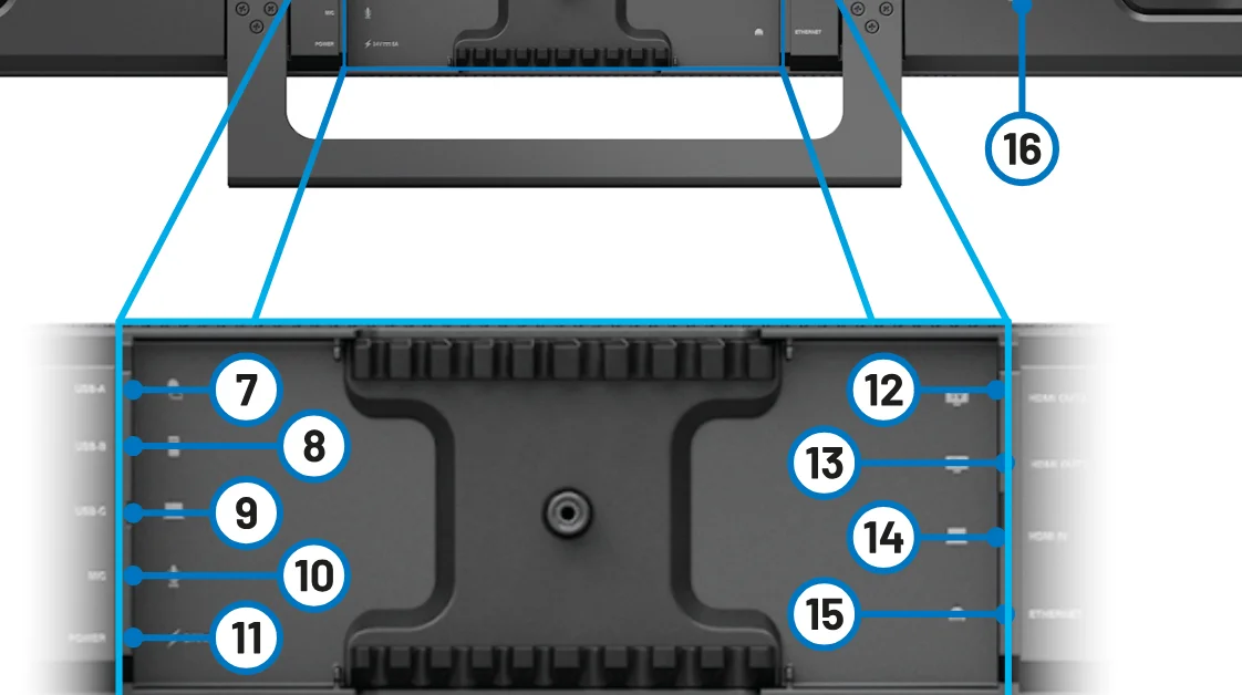
Side View
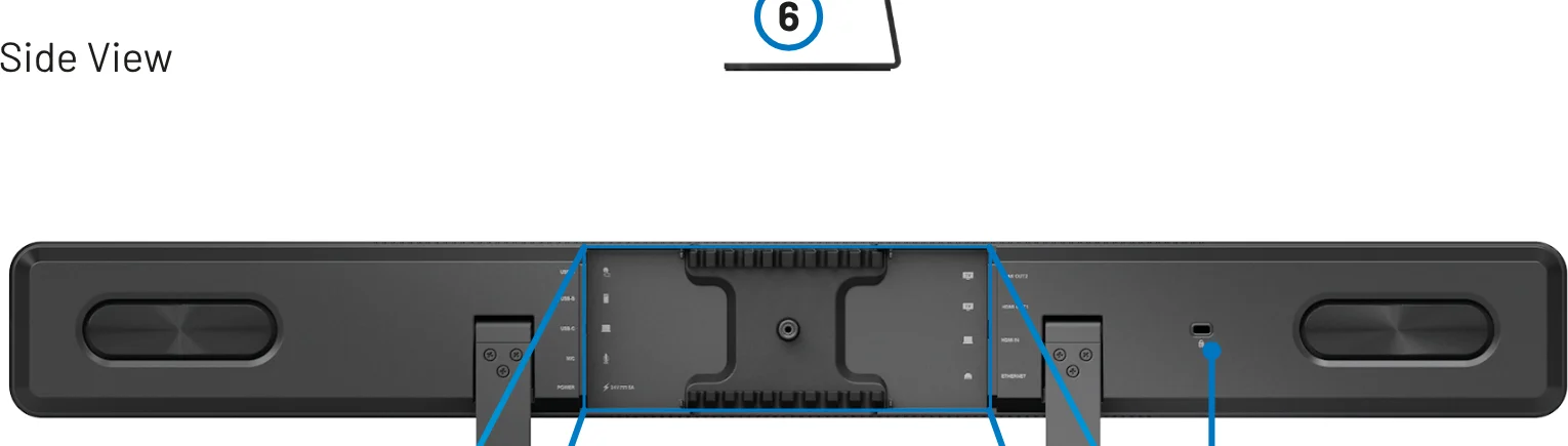
Back View
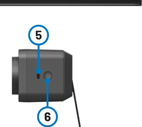
Close-Up
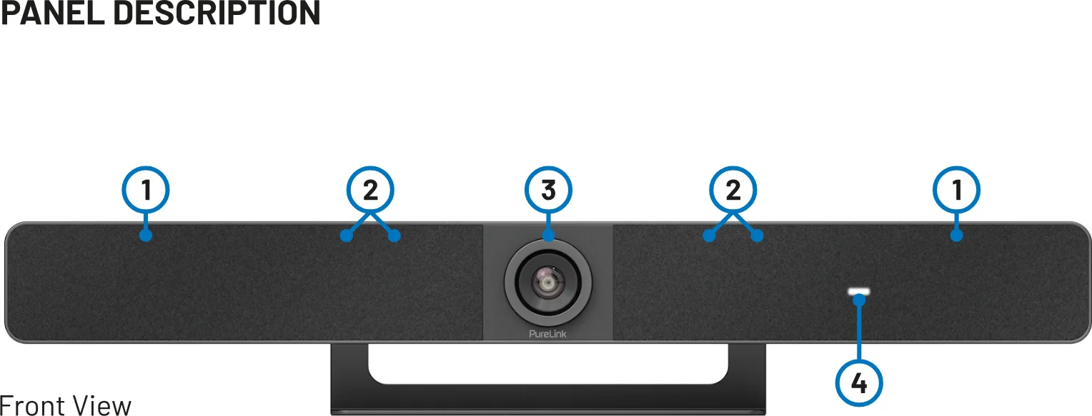
| No. | Name | Description |
|---|---|---|
| 1 | Speaker | 2 x Speakers for audio signal output. |
| 2 | Microphone | 8 x Linear microphone arrays for picking up sound. |
| 3 | Lens | Camera lens. |
| 4 | Status LED | Blinking orange: The device is booting. Lighting white: The device is working properly. Blinking white: The device is in standby state. Blinking white very quickly: The device is being upgraded. Breathing and lighting white: The device is in sleep state. Lighting red: The device’s microphone is muted. Blinking blue: The device is in pairing state. |
| 5 | USB-C | Connect to the Dongle for pairing |
| 6 | Pairing Button | Press and hold this button for more than 2 seconds to start pairing with the remote controller. |
| 7 | USB-A | USB 3.0 Type-A port. Connect to a USB device such as touch screen. |
| 8 | USB-B | USB 3.0 Type-B port. Connect to the room PC for meetings |
| 9 | USB-C | USB 3.0 Type-C port. USB PD: 60W max Connect to the laptop for meetings. |
| 10 | MIC | Connect to an external microphone. |
| 11 | DC 20V/6A | Connect to the power adapter provided for DC 20V/6A input. |
| 12 | HDMI OUT2 | HDMI 1.4 type-A female port. Connect to a HDMI display device or a capture card of the room PC. |
| 13 | HDMI OUT1 | HDMI 2.0 type-A female port. Connect to a HDMI display device or a capture card of the room PC. |
| 14 | HDMI IN | HDMI 1.4 type-A female port. Connect to an HDMI source. |
| 15 | ETHERNET | Connect to a network device (e.g. network switch, wireless router, computer, etc.) for Airplay Mirroring signal input and LAN control (Web GUI & Telnet API). |
| 16 | Kensington security slot |
Installation
Note: Before installation, ensure the device is disconnected from the power source.
To install the device on the wall
- Drill holes on the wall you desire, then insert the expansion screws provided into the wall. Secure the wall hanging bracket on the wall using the mounting screws provided.
- Remove the stand from the device.
- Screw the wall-mounted bracket to the device.
- Attach the device’s wall-mounted bracket to the wall hanging bracket on the wall.
Application
Note: Before wiring, disconnect the power from all devices.During wiring, connect and disconnect the cables gently.
BYOM
One Type-C full function cable (optional) can support DP 1.2, USB 3.0, USB 2.0 and PD (max 60W).
The second connection method is to use the standard HDMI and USB-A & USB-B cables.
- USB-C HDMI
- Laptop VL-VB300-PRO TV
- HDMI
- USB-A to USB-B
- HDMI 1
- HDMI 2
- Laptop VL-VB300-PRO
- TV
- TV
ZOOM ROOM + BYOM
Note: After the device is connected to a computer, it can be detected by the system and specific applications with the following name:
Model: VL-VB300-PROCamera/Speaker/Microphone: VL-VB300-PRO
- HDMI
- HDMI USB 3.0
- TV
- TVUSB Capture Card (Certified by Zoom)
- VL-VB300-PRO Room PCLaptop
- Dongle
- Internet
- HDMI
- Ethernet
MICROPHONE CASCADING
Note: Desktop installation is recommended and up to 5 units of VL-MIC110 can be cascaded. The total length of all deployed CAT6 cables shall not exceed 26 meters.
Max. 18m CAT6 cable between the first VL-MIC110 and USB-to-RJ45 adapterRecommended 2m CAT6 cable between adjacent VL-MIC110 microphones
- VL-VB300-PRO
- VL-MIC110 (1)
- VL-MIC110 (2)
- VL-MIC110 (4)
- VL-MIC110 (3)
- VL-MIC110 (5)
- Mini USB to RJ-45
- ConnectorRJ-45
- Ethernet Cable
- Ethernet Cable
- Ethernet Cable
- Ethernet Cable
- MIC
Key Functions
If you’re working on a PC and want its apps and content to be shown on another screen you’ll want to consider mirroring your PC’s screen to that screen.
With screen mirroring support, the device allows you to share your mobile devices’ content wirelessly on any HDMI displays over Airplay Mirroring, Miracast and Dongle. In this manual, mobile devices available for screen mirroring are referred to as “screen mirroring source”, which include Apple devices (iPhone/iPad/Mac), Android phones, Windows PCs and Dongles.
Screen Mirroring Over Airplay (Apple Devices)
- Connect your iPhone/iPad/Mac to the soft AP of the device. Soft AP SSID: as same as the switcher’s device name and can be obtained from OSD at the upper right of the display screen. By default, it is set as VL-VB300-PRO. Password: set through Web UI or Telnet API and can be obtained from OSD at the bottom right of the display screen. By default, it is set as 12345678.
- Open Control Center on your Apple device, tap Screen Mirroring to select appropriate mirroring device (default device name is VL-VB300-PRO) from the pop-up menu.
- To disconnect Apple device from the switcher: click Stop Mirroring, the display stops displaying your device’s screen.
Screen Mirroring Over Miracast (Android Phones & Windows PCs)
For Android mobiles (take Samsung Galaxy series for example):
- Enable the Wi-Fi or WLAN feature of your mobile device.
- On your mobile device, swipe down from the top and tap the cast icon or SmartView icon to select appropriate mirroring device from the pop-up CONNECT menu.
- To disconnect mobile phone from the switcher: click “DISCONNECT” on your mobile phone’s screen.
Note: The icon, instruction and entrance of the Miracast function may vary on different Android mobiles, please refer to your mobile’s manual to get accurate instruction.
If you fail to use Miracast function, please disable the mobile’s Wi-Fi and enable it later, or restart the mobile if necessary.
For Windows PC (Windows 10 or Higher)
- Enable the Wi-Fi or WLAN feature of your PC.
- On your PC, press the combination keys to select appropriate mirroring device from the pop-up menu.
- To disconnect PC from the device: click Disconnect, the display stops displaying PC’s screen.
Note: The icon and interface of the Miracast function may vary on different computers.Some Windows 10/11 computers may fail to perform screen mirroring over Miracast due to compatibility issues.
Tip: Both the Airplay mirroring and Miracast support access code. If you see the PIN entry window appears on your devices, input the access code which can be obtained through OSD. (See “OSD” section for more information.)
Screen Mirroring Over Dongle
A Dongle enables users to share laptop’s content on a display wirelessly without even installing an application.
To pair a Dongle:
- Pair a Dongle with the device. Connect a Dongle to the PAIRING port of the device for pairing. Once pairing is completed, “Pairing successful” appears on the display screen.
- Connect the Dongle to a laptop. Connect the Dongle to the laptop, it will start running and connecting to the device’s soft AP. Once the Dongle connects to the device successfully, the Dongle LED stops blinking and starts lighting constantly.
- Now press the Dongle’s projecting button, you can share your laptop’s screen on the display immediately. Press and hold the button for at least 5 seconds, you will have your laptop’s screen displayed in full screen.
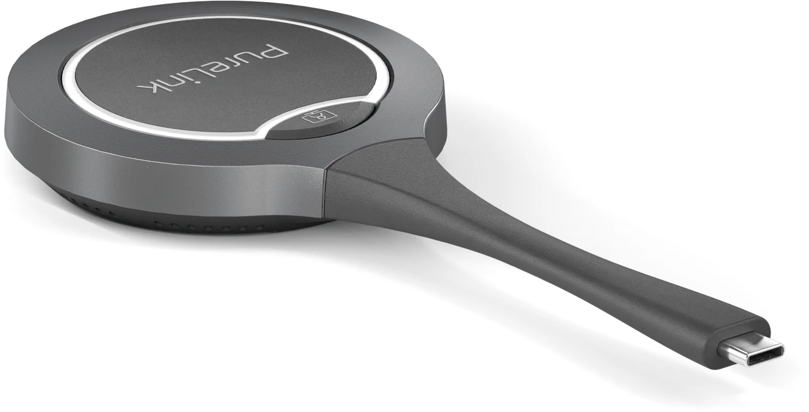
Note: For more information about the Dongle, see its user guide.
Wireless Conference
Wireless Conference function enables a laptop to access the USB conference peripherals (such as a USB camera, a USB speakerphone, etc.) attached to the switcher wirelessly through a Dongle.
How to use this feature:
- Pair between the switcher and the Dongle. Connect the Dongle to the switcher’s PAIRING port to pair two devices.
- Insert the dongle into the laptop. A pop-up will appear in the bottom right corner of the desktop. Click it, and in the next pop-up, select "Run PureLink-Share-Setup.vbs" to install the application.
- The installation process will run in the background and the application will start automatically after the installation is successful.
- Connect the Dongle to the laptop’s USB-C port.
Note: The Dongle will be ready to transmit and receive signals in a few seconds.
Please make sure the USB-C port of the laptop supports audio and video output.
- Press the Wireless Conference button on the Dongle to connect between the laptop and the USB devices wirelessly. Now you can access the USB camera and the USB speakerphone through the laptop as you wish.
Multi-View
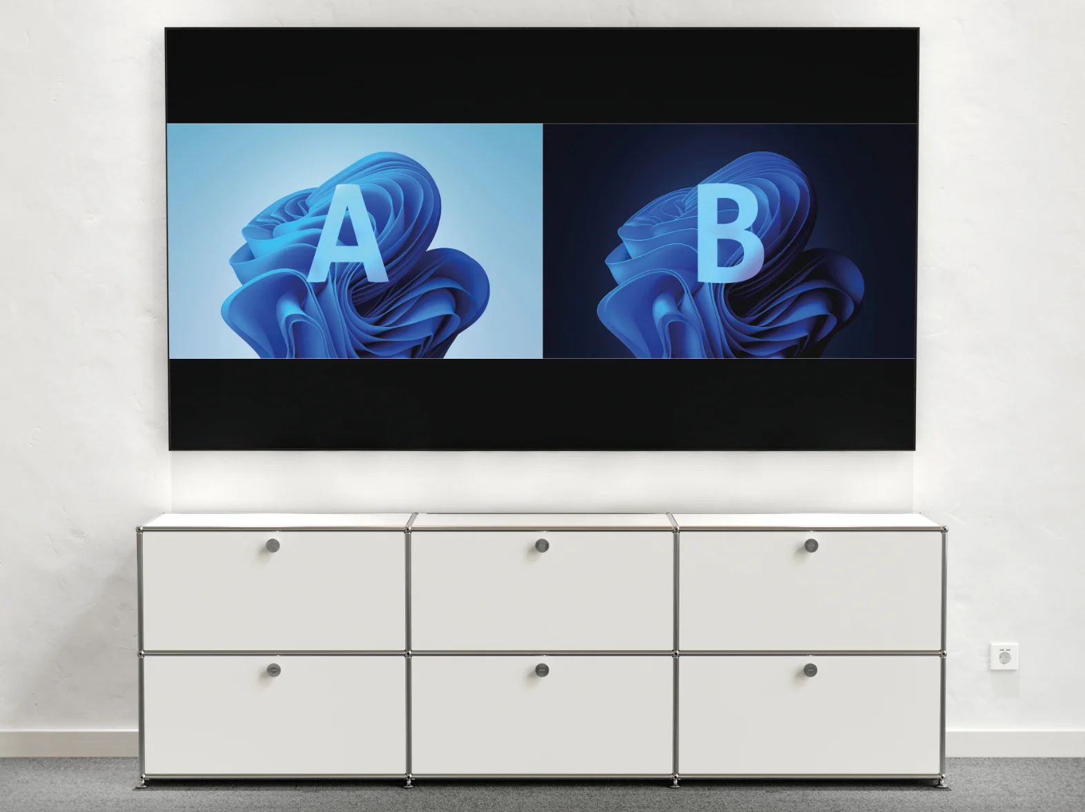
By default, the VL-VB300-PRO allows dual-view layout feature when 2 active sources and single screen.
Automatic Switching
The device supports automatic switching of input signals and display layouts. The automatic signal switching allows you to easily and quickly select desired sources, which follows the Last-In-First-Out rule as below:
- When a video source is being displayed in full screen, connect one more video source to the device, the device will automatically switch to the Dual-View layout.
- When two video sources are being displayed in Dual-View mode, connect an additional video source to the switcher, the latest input source will replace the source present longer on the screen.
- When two video sources are being displayed in Dual-View, stop displaying one video source, the device will automatically switch to the full-screen Single-View.
Dual-Displays
The device supports dual-display output with the following rules:
With one active video source: the source outputs to HDMI OUT1, while HDMI OUT2 displays the Guide Screen.
If the first source is disconnected and a second source is plugged in: the new source outputs to HDMI OUT1, with Guide Screen on HDMI OUT2.
When two video sources are active: the two sources are separately displayed on the two outputs. Upon connection of a third active source, the first source drops out HDMI outputs will show the second and third sources respectively.
Guide Screen
The device outputs Guide Screen image when no video source is selected or being output. The Guide Screen can be personalized on the device’s Web UI page to convey customized connection instructions.
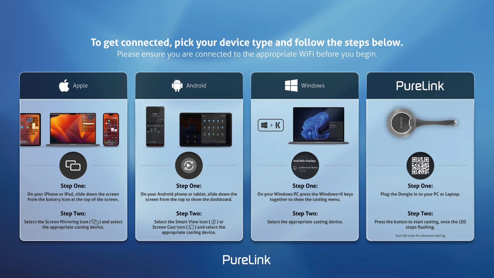
Guide Screen is accessible in the following cases:
Automatic switching:
Disconnect all video sources from the device, the Guide Screen appears automatically.Manual switching:
Log on to the web UI page to select Guide Screen for the HDMI outputs.For more information see the State & Switch section.Send API command through telnet to the device to show the Guide Screen.
For more information see the separate API documentation.
Tip: This Guide Screen image can be changed though Web UI, for more information refer to System Settings section.By default, if the device is outputting Guide Screen for 60 seconds, a 60-second OSD countdown will appear on the Guide Screen. When the countdown reaches zero, the device will enter standby status.
OSD
The device comes with OSD (On-Screen Display) support, enables users to view basic information of the device, including video source channel, access code, device name and IP address, etc. Here are two different OSD examples.
Example 1: Full screen mode
- IP Address of the switcher
- WiFi Password of the switcher
- Device Name of the switcher
- Access Code of the switcher
- Video Source Name
Example 2: Dual-View Mode
Note: When the device outputs Guide Screen image, the OSD is shown all the time.When the device outputs specific video sources, the OSD will display on the display device for 10 seconds and then disappear.By default, the access code is set as blank, therefore the OSD doesn’t display the access code. If you want to set access code, please see BYOD > Access Code section for more information.
- AIRPLAY1 HDMI IN
- IP Address of the switcher
- WiFi Password of the switcherVideo Source NameVideo Source Name
- Device Name of the switcher
- Access Code of the switcher
- Video Source Name
Use Remote Controller
When using the remote controller, pressing the left or right arrow buttons will move the selection cursor between the two screens. Pressing the Home button will switch the selected screen to Single Screen display mode. The unselected wireless video source will be disconnected, while wired video sources will remain connected; however, all sources must be reconnected manually to re-enter Split Screen mode.
Pairing with remote controller
The device can be controlled by the remote controller provided, after they have been successfully paired with each other.
- Press and hold the pairing button on the enclosure’s left side, the status LED will blink blue, which indicates that the device enters pairing mode.
- Press any button on remote controller, "Remote Control Connected" will appear on the display screen, indicating that paring between the remote controller and the device is successful. Now you can use the remote controller to control the device with ease.
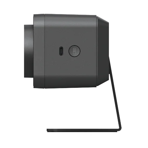
The following briefly introduces the functions of the remote controller buttons:
| Button | Function |
|---|---|
| Pairing | Press and hold the button for 2s to make the device to start paring. |
| Answer | N/A |
| Hang up | N/A |
| Home | Press to go back to the default camera view (available only when Tracking mode is off). Press and hold the button for 2s to show OSD that includes IP address, model name, etc. |
| Navigation | Press to perform ePTZ (only available when Tracking mode is off). When the device is connected to a display via a single HDMI OUT port and is in dual-screen mode, you can use the left and right navigation buttons to switch between the two screens. Press the “Home” button will make the selected screen display in full screen. This operation takes priority over ePTZ. ePTZ control will resume only after exiting Split Screen mode. |
| presets | When Tracking mode is off: Press and hold for 3s to save current camera view to preset 1 or 2. Press to switch the camera view to preset 1 or 2 |
| Mute/Unmute | Press to toggle between mute and unmute the microphone of the device. |
| Volume | Press to adjust the volume. Press and hold to adjust the volume continuously. |
| Tracking Mode | Press to toggle among Auto Framing, Speaker Tracking, Presenter Tracking, Individuals Gallery and Off. |
| Zoom | Press to adjust the zoom. Press and hold to adjust the zoom continuously. |
Press and hold the pairing & hang up buttons for 3s, the remote controller will enter pairing mode.
Web UI
The Web UI designed for this device allows for basic settings. It can be accessed through a modern browser, e.g. Chrome, Safari, Firefox, etc.
- Connect the Ethernet port of the device to a local area network. (Ensure there’s a DHCP server in the network so that the switcher can obtain a valid IP address.)
- Connect a PC to the same network as the device.
- Input the device’s IP address in the browser and press Enter, the following window will pop up. Note: Default IP mode for this device is DHCP.
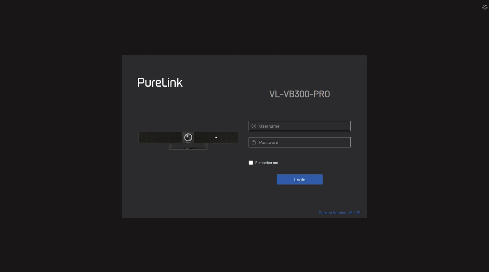
- Input the user name and password (default user name & password: admin) and click Login to enter the main page.
The main page includes Overview, Camera, Settings and Support tabs.
- Overview – offers basic information of the device.
- Camera – offers settings of camera parameters.
- Settings – offers basic settings of video, Wi-Fi, BYOD, etc.
- Support – offers firmware update function and device information.
Click to open / close help mode. Once opened, some descriptions of the functions will be displayed below the options or buttons. Click to toggle between black and white backgrounds. Click to exit and go back to login page.
OVERVIEW
This page offers firmware version and status of output timing and HDCP settings for the device.
| Item | Description |
|---|---|
| Preview Button | Click to start preview mode, where the video feed from the camera will be displayed in this frame for real-time preview (note that the camera will be unavailable for use in other software during preview). All settings will be reflected live in this view. To exit preview mode, simply move the mouse to the center of the screen and click the black square. |
| AI Region | Enable users to specify the area for the AI tracking active. |
Tracking Mode
Auto Framing (default setting) is an AI feature to zoom, pan, and tilt intelligently so that everyone in the room is perfectly located in the picture.Speaker Tracking is an AI feature to intelligently focus on the person who is talking. When more than one person is speaking, it will automatically switch between speakers.Presenter Tracking is an AI feature to intelligently track the presenter, so that the presenter can always be in the best position on the screen even when constantly moving.Individuals Gallery is an AI feature to intelligently frame up to four attendees and keep each attendee in the appropriate scene, and then merge and combine them into a single frame. More than 4 participants, it will work as auto framing mode automatically.Off: When tracking mode is set to off, users can adjust the focal length to zoom in or out of the scene by moving the circular slider. To pan the camera view up, down, left, or right, click the respective arrow keys on the left side.
Tracking Effect
Tracking effect is available when Auto Framing is enabled.Smooth (default setting): The tracking image moves smoothly in the frame.Immediate: The tracking image switches from one to another immediately in the frame
Tracking Speed
Tracking speed is available when Auto Framing is enabled.Slow (default setting) / Normal / Fast When tracking mode is off, users can adjust the focal length to zoom in or out of the scene by moving the circular slider. To pan the camera view up, down, left, or right, click the respective arrow keys on the left side
Preset 1/2
When tracking mode is off, click “Set” to save current camera view to this preset. Click “Load” to upload the saved camera view from the selected preset.
Mirror
Mirror image function.On: To flip the image horizontally.Off (default): Not to flip the image horizontally
Powerline Frequency (Anti Flicker)
Change the frequency to prevent flicker in the video.50Hz (default setting) / 60Hz
HD
On (default): Turn on for better image quality.Off: Turn off for better compatibility.
Camera Resolution
Select camera resolution among 4K and below (default), 1080P and below and 720P and below.When HD is set to on:4K and below: resolution supports from 720P to 4K;1080P and below: resolution supports from 720P to 1080P;720P and below: resolution supports 720P.
WDR
Use the slider to set camera’s WDR. Default value: 0, range: -7~7.
General Settings
Device Name
Device Name: VL-VB300-PRO
The device name must be 1 to 31 characters long, using only letters, numbers, spaces, hyphens, or underscores. It must start and end with a letter or a number.
Note: Changing the device name will modify the SSID at the same time, and the Type-C Dongle needs to re-pairing.
Apply
Settings
IP Method: Static DHCP
IP Address: 192.168.101.12
Subnet: 255.255.254.0
Gateway: 192.168.100.1
Primary DNS: 192.168.100.11
Secondary DNS: 8.8.8.8
Apply
Note: LAN Module will automatically reboot after changing Network setting.
IP Conflict Detection
IP Conflict Detection:
Video Settings
Device Name
Redefine the device name to an easy to remember one
Note: The name must be 1~20 characters in length, including letters, numbers, “_” or “-”
• By default, it’s set as VL-VB300-PRO.
• Apply: Click to save and perform above settings
Note: The device name is as same as the soft AP SSID. If you change to a new device name, you need to re-pair Dongle with this device as well
IP Method
- IP Method: Static / DHCP (default setting).
- IP Address: Set IP address manually when Static mode is selected.
- Subnet: Set subnet mask manually when Static mode is selected.
- Gateway: Set gateway address manually for the device to communicate with another network that uses different communication protocols when Static mode is selected.
- Primary DNS / Secondary DNS: Set Primary DNS / Secondary DNS manually when Static mode is selected.
- Apply: Click to save and perform above IP settings. (LAN module will reboot automatically once IP settings are changed.)
Note: When "Static" is selected, please ensure your PC is in the same network segment as the camera.
Please wait for 2-3 minutes for the camera's LAN module to reboot and reconnect after the network setting is changed.
IP Conflict Detection
Set IP conflict detection function to on/off. The default setting is on. When IP conflict detection is enabled, an OSD prompt is displayed when an IP address conflict is detected
Camera Out
| HD Mode: | |
|---|---|
| Camera Resolution: | 4K and below |
| Output | |
| Timing: | |
| HDCP: | |
| HDMI OUT1: | Auto HDCP2.2 |
| HDMI OUT2: | Auto NO HDCP |
CEC
| CEC: | |
|---|---|
| HDMI OUT1: | |
| One Touch Play: | 40 04 |
| Standby: | ff 36 |
| HDMI OUT2: | |
| One Touch Play: | 40 04 |
| Standby: | ff 36 |
Note: CEC command just supports Hex format with a maximum of 18 byte (Example: 40 04).
Apply
Load Default
CEC Test
One Touch Play
Standby
Audio Settings
Wi-Fi Settings
BYOD Settings
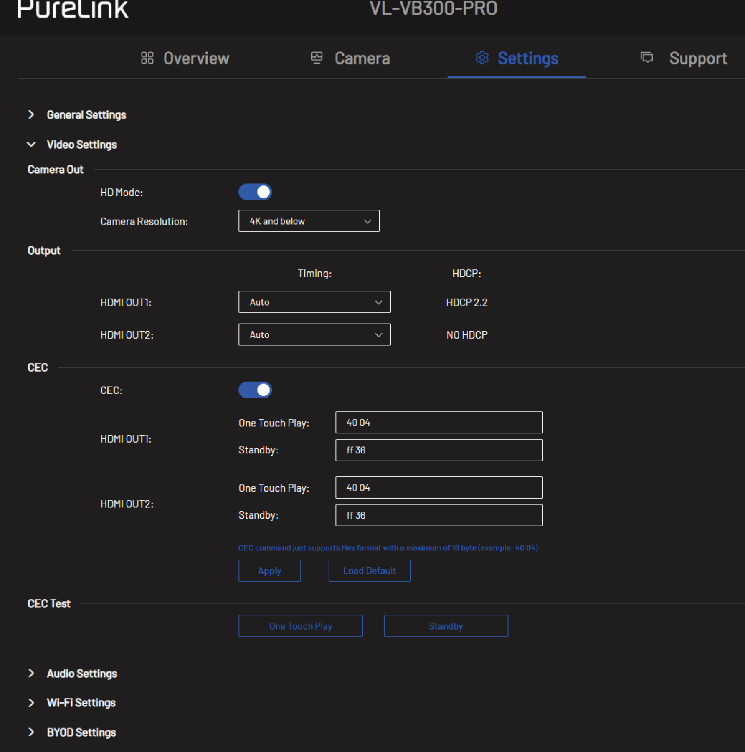
Camera Out
- HD Mode: On (default): Turn on for better camera image quality.
- HD Mode: Off: Turn off for better camera compatibility.
Camera Resolutions
- Set output resolution for the device. Three options are offered:
- 4K and below
- 1080p and below
- 720p and below
Timing (HDMI)
Set the resolution and FPS (frames per second) for each of the HDMI outputs. Available resolutions and timings:
3840x2160p 30Hz, 1920x1080p 60Hz, 1920x1200p 60Hz, 1680x1050p 60Hz, 1600x1200p 60Hz, 1440x900p 60Hz, 1366x786p 60Hz, 1280x800p 60Hz, 1280x720p 60Hz, 1280x1024p 60Hz, 1024x768p 60Hz, 800x600p 60Hz, 720x480p 60Hz, 640x480p 60Hz
HDCP
Shows HDCP of HDMI OUT 1/2.
CEC
- CEC On (default setting)/Off: Select to enable/disable CEC control.
One Touch Play
Enter the CEC one touch play command in hex of the controlled display device for each HDMI output. For more information about the command, see the user guide of your display device.
By default, it’s set as “80 04” for HDMI 1 and “40 04” for HDMI 2.
Standby
Enter the CEC standby command in hex of the controlled display device. For more information about the command, see the user guide of your display device.
By default, it’s set as “80 36” for HDMI 1 and “ff 36” for HDMI 2.
Apply Click to save and perform above settings.
Load Default Click to load default settings.
CEC Test One Touch Play/Standby: Click to test if command setting takes effect.
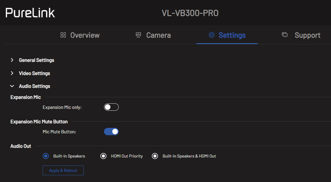
Expansion Mic Only
Turn on or off (default) to choose to only use the expansion mic.
Default setting: Off.
Mic Mute Button
Turn on (default) or off.
Audio Out
Choose where the audio is output: Built-in speakers, HDMI OUT Priority or built-In speakers & HDMI OUT.
Build-in Wi-Fi
- Channel:
- Auto (default setting): The device selects a wireless channel for itself automatically.
- Manual: Assign a wireless channel for the device manually.
- Apply: Click to save and perform above settings.
Soft AP
- Soft AP: On (default setting) /Off.
- Soft AP Router: On (default setting) /Off.
- Password: Configure the soft AP password. By default, it is set as 12345678
- Apply: Click to save and perform above settings.
BYOD
- Miracast over Infrastructure: Please note that if the device is connected via Miracast over infrastructure, the Access Code will not be required.
Access Code
- Auto
- Manual 8613
- 0000-9999 or blank
- Apply
Guide Screen
- Guide Screen: Select the jpeg files
- Image in jpeg/jfif formats with 1920x1080 resolution
- Upload Restore the Default Image
OSD
- OSD:
- Font: PureLink
- Font Color:
- Background Color:
- Background Transparency: 75%
- Text
- Countdown Position: Default
- Apply Reset OSD to default
BYOD
- On (default setting) / Off
Miracast over Infrastructure
- On / Off (default)
- If the device is connected via Miracast over Infrastructure, the Access Code will not be required.
Access Code
The access code is used to help prevent users from accidentally connecting to an unintended device and protect from an unauthorized access.
- Auto: The device will randomly generate a four-digit access code in the following cases:
- The device switches to Guide Screen for output.
- The device reboots.
- Manual: Select to input a four-digit code.
- Access Code is ON by default.
Apply Click to save and perform above settings.
Guide Screen
- Click to select a Guide Screen image in .jpg format of 1920x1080 and upload to the device.
- Restore the default Image: Click to restore the guide screen to the default image.
OSD
- On / Off (default)
- Font Choose Font Style.
- Font Color Choose the color of the font on the OSD.
- Background Color Choose the color of the background on the OSD.
- Background Transparency Choose the transparency level of the background on the OSD
- Text Preview your color and font choices
- Countdown Position Default / Center
- Apply / Reset OSD to default Choose Apply to apply your choices or reset back to default.
Scheduling Settings
NTP (Network Time Protocol)
- On/Off (default)
Date/Time
If not using a NTP, manually set the date & time for scheduling features to work properly.
Timezone
Set the proper timezone for the location of the system.
NTP Server
Set the NTP server address.
Apply Click to save and perform the NTP/Schedule settings.
Startup
- On/Off (default)
- Days Choose which days of the week the schedule should be used.
- Time Set the time for which the system will be on and when it will turn off.
- Apply Click to save and perform the startup settings
Screen Off
- On / Off (default)
- Delay Time ‘0’ means the countdown 60s will appear immediately, and the ‘n’ means the countdown 60s will appear after ‘n’ minutes.
Reboot
- On/Off (default)
- Days Choose which days of the week reboot should be used.
- Time Set the time when the system should reboot
- Apply Click to save and perform the reboot settings.
Privacy & Security
XYTE CLOUD
For more information on xyte cloud visit www.xyte.ai
Telnet Authentication
- On/Off (default)
Connect to Cloud
- On/Off (default)
Cloud Server Status
Connection status of the Xyte Cloud Server. Click the reload icon to try again
System Settings
Login
Set a new password to login Web UI.
Appl Click to save and perform above settings.
Configuration
Import or export the configuration files.
System
- Factory reset: Click to reset the device to factory defaults.
- Reboot: Click to reboot the device.
- Export Log: Click to export log file to local PC.
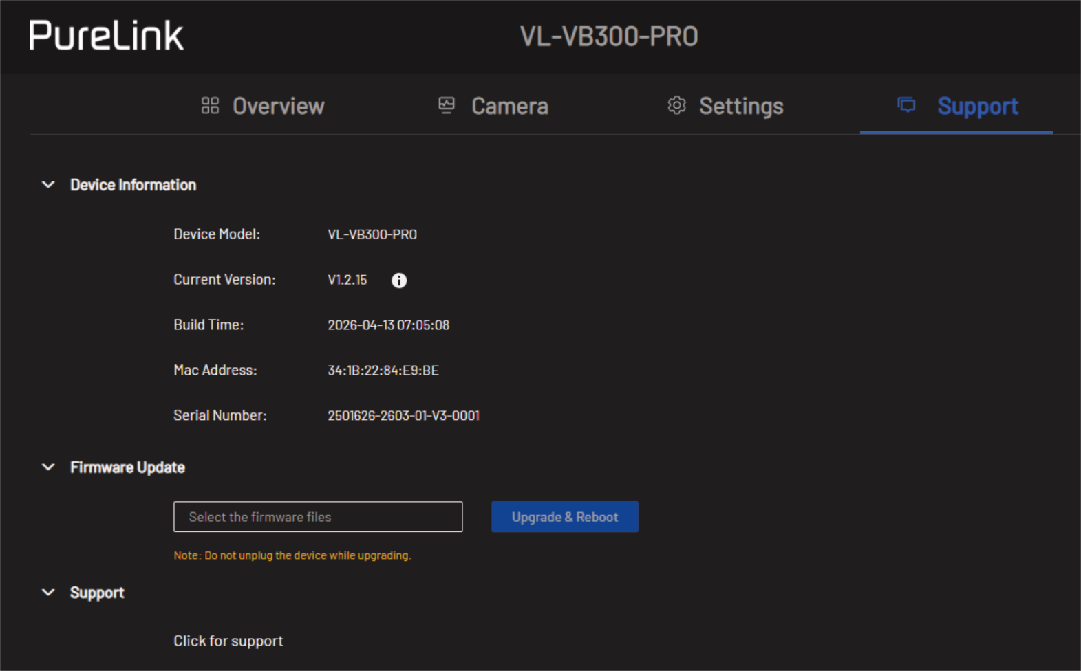
Support
Device Information
Displays device model and firmware information
Firmware Update
Select the firmware file and upload it for upgrade
Support
https://url.purelink.de/contact
Troubleshooting
For further support or questions please contact us under: https://url.purelink.de/contact
Or scan the QR-code:
- The key on remote has no reaction, how to resolve? Try to replace the battery in remote.
- Press the Home button on remote, the picture of camera can't return to panorama, how to resolve? Please make sure the AI mode is off, this function is only effective in manual mode.
- The HDMI OUT of VL-VB300-PRO no video output, how to check? To check if the cables (HDMI IN / HDMI OUT / Type-C) have been plugged properly, re-plug the cables. To check if the display device has selected the correct input.
- Why can VL-VB300-PRO only output at 720p when using thirdparty video conferencing apps like Zoom, Microsoft Teams, etc.? This is due to the limitations of third-party software, like Zoom and Microsoft Teams only support 720p now.
- The Camera/Speaker/Mic of VB300 can't be recognized or the picture from camera is abnormal, how to resolve? Try using a different USB port on your computer. Try using a different USB cable.
- The audio from Win10/11 system PC is stereo but the left and right speaker of VB300 is mono, how to resolve? Click Win 10/11 system PC's start button, settings button, and select easy to use, select audio, set mono audio OFF.
- After connecting a new device to PC, PC's audio doesn't output from VL-VB300-PRO, how to resolve? Open the settings page of PC, in selecting output device select VL-VB300-PRO.
- Win+k doesn’t work on Windows PC. Please try to reboot the Windows PC.
CE Conformity
PureLink GmbH hereby declares that this product is in compliance with the essential requirements and other relevant provisions of the RED Directive 2014/53/EU and the RoHS Directive 2011/65/EU amended by 2015/863/EU.
PureLink GmbH hereby declares that this product is in compliance with the essential requirements of the Electromagnetic Compatibility Regulations 2016 and all other applicable UK regulations.
The EU Declaration of Conformity is available here:
www.purelink.de
Disposal of the Device
WEEE-Reg.-Nr. DE 93847290
According to the European WEEE Directive, electrical and electronic equipment may not be disposed of with household waste. As a consumer, you are obliged to return electrical and electronic equipment free of charge at the end of its service life to the public collection points set up for this purpose or to the point of sale. Details on this are regulated by the respective national law.
The symbol on the product, the instructions for use or the packaging refers to these regulations. Recycling old appliances in this way is an important contribution to the protection of our environment.
Battery Recycling information
Batteries and accumulators must not be disposed of in household waste. Please dispose of used batteries and accumulators properly, following local regulations.
Consumers in Germany are required by law to take all batteries and accumulators to a collection point in their community/borough or to retailers to have them disposed of in an environmentally friendly way. Otherwise they pose a potential risk to the environment and to human health.
Disclaimer and liability
PureLink GmbH will not be held liable, nor provide any warranty for damage resulting from improper installation, assembly and use of the product, or failure to observe the operating instructions and/or safety instructions.
Trademark
Product model and logo are trademarks. All other trademarks mentioned in this manual are acknowledged as the property of the trademark owners. No part of this publication may be copied or reproduced without prior written permission of their respective owners.
Legal & Compliance
Product identification
Model: VL-VB300-PRO – manual version 1.0
Warranty and liability
The manufacturer grants the full statutory warranty on all new devices. As the manufacturer has no influence on installation, the warranty only applies to the product itself. If you detect a fault or damage, please contact your dealer and provide your sales slip or invoice as proof of purchase.
The manufacturer is not liable for damage to persons or property caused by improper installation, operation or maintenance not described in this manual. Do not alter or modify the product or its accessories. Any use other than described in this manual is not permitted and voids warranty and guarantee.
Packaging
Dispose of packaging separately by material (paper/cardboard, plastics) via the local collection systems. Keep packaging material away from children – risk of suffocation. Packaging register LUCID: DE5958616449295.