
Actif
PT-HDBT-1021KVM-TX
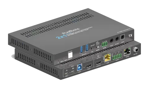
Émetteur de collaboration HDBaseT 3.0 2x1 18 Gbps
Le PT-HDBT-1021KVM-TX est un transmetteur de collaboration 2x1 HDBaseT 3.0 avec des entrées HDMI et USB-C, prenant en charge des signaux HDMI 2.0 non compressés jusqu'à 4K 60Hz (4:4:4) via un câblage HDBaseT sur des …
ManuelCommandes (TCP/IP)SpécificationsFiche techniqueCEInterfaces de contrôle disponibles. Développez un type actif pour afficher le tableau complet des commandes.
Aucune commande correspondante.
Commandes RS23227 commandesActif
Source : manuel, chapitre RS232 Control, page 24
| Commande | Description | Exemple | Réponse | |
|---|---|---|---|---|
| STA. | Rapporter l’état du système. | PT-HDBT-1021KVM-TX 2x1 18G KVM Extender over HDBaseT 3.0 FW Version: V1.0.0a Power On! Front Panel Unlock! Local RS232 Baudrate Is 9600! MAC:50-2E-AB-0C-DE-7C! GUI IP DHCP:OFF! GUI_IP:192.168.0.178! GUI_SM:255.255.255.0! GUI_GW:192.168.0.1! HDMI Out Switch Auto Mode! HDMI Out Switch To 01! Input 01 EDID From 03 EDID! Input 02 EDID From 03 EDID! Out HDCP Follow Output! Tx Loopout Down Scale On! Trigger Mode Is 5V! Audio De-embedding On! Device Power Mode Is Follow Host! | ||
| RST. | Réinitialisation d’usine. | Factory Default! | ||
| Baudrate[x]. | Définir le débit en bauds sur [x]. [x] peut être 2400, 4800, 9600, 19200, 38400, 57600 ou 115200. Exemple : Baudrate9600. | Set Local RS232 Baudrate To 9600! | ||
| POWON. | Allumer le système. | Power On! | ||
| POWOFF. | Mise en veille du système. | Power Off! | ||
| HDMI[X]. | Sélectionner X comme source d'entrée vidéo. [X] peut être de 1 à 2. | HDMI Out Switch To 01! | ||
| HDMIA. | Activer le mode de commutation automatique. | HDMI Out Switch Auto Mode! | ||
| HDMIM. | Activer le mode de commutation manuelle. | HDMI Out Switch Manual Mode! | ||
| AOUTON. | Activer la désinsertion audio. | Audio De-embedding On! | ||
| AOUTOFF. | Éteindre la désinsertion audio. | Audio De-embedding Off! | ||
| EDID/[XX]/[YY]. | Render the video source that connected to the [xx] port on the transmitter to use the EDID of [yy]. [XX] represents the video input port. 00: represents all the input ports. 01: represents No. 1 video input port. 02: represents No. 2 video input port. [YY] represents the included EDID as below: 01: Use the EDID of the screen that connect to the transmitter (TX). 02: Use the EDID of the screen that connected to the receiver (RX). 03:1920x1080@60 8bit Stereo (default) 04:1920x1080@60 8bit High Definition Audio 05:3840x2160@30Hz 8bit Stereo Audio 06:3840x2160@30Hz Deep Color High Definition Audio 07 | 3840x2160@60Hz 4:2:0 Deep Color Stereo Audio 08 | 3840x2160@60Hz Deep Color Stereo Audio 09 | 3840x2160@60Hz Deep Color High Definition Audio 10 | 3840x2160@60Hz Deep Color HDR LPCM 6CH 11 | User-defined EDID1 12 | User-defined EDID2 13 | User-defined EDID3 14 | User-defined EDID4 | EDID/01/01. | Input 01 EDID Upgrade OK By 01 EDID! | |
| EDIDUpgrade[xx]. | Le port série met à jour les données EDID. [xx] représente le port d'entrée, la valeur peut être 00, 01, 02, U1, U2, U3 et U4. [xx]=00-02 signifie personnaliser l'EDID du port d'entrée correspondant (l'EDID bascule vers l'EDID personnalisée après personnalisation et ne sera pas enregistrée dans l'appareil), 00 signifie opérer sur tous les ports d'entrée, 01-02 signifie entrée 01-02. [xx]=U1-U4 signifie EDID intégrée personnalisée (peut être enregistrée dans l'appareil et rappelée à tout moment), une seule EDID intégrée peut être personnalisée, et l'EDID actuelle utilisée après la personnalisation ne basculera pas vers l'EDID personnalisée. Après réception de la commande, l'appareil invitera à envoyer le fichier EDID. Le format du fichier doit être .bin dans les 10 secondes (afin d'assurer une réception normale des données, toutes les mises à jour EDID d'entrée XX/définies par l'utilisateur sont OK !) | Input XX/User Define EDID Upgrade OK! | ||
| LOCK. | Lock front panel. | |||
| UNLOCK. | Unlock front panel. | |||
| SetDevicePowerMode[XX]. | Définir le mode d'alimentation : XX = 00-01 00 : Suivre l'hôte 01 : Toujours activé | Set Device Power Mode To Follow Host! Set Device Power Mode To Always On! | ||
| SetGuiIP:xxx.xxx.xxx.xxx. | Set GUI IP address. | SetGuiIP:192.168.0.18. | SETGUIIP:192.168.0.18! | |
| SetGuiIP_DHCPON. | Enable DHCP for GUI IP address. | |||
| SetGuiIP_DHCPOFF. | Disable DHCP for GUI IP address. | |||
| /+[X]:XXX. | Contrôler les appareils environnants qui y sont connectés. [X] représente la vitesse en bauds ; elle peut être de 1 à 7. 1—2400, 2—4800, 3—9600, 4—19200, 5—38400, 6—57600, 7—115200 XXX représente le code ASCII. | /+3:123456. | 123456 | |
| SIGNALTRG[XX]MODE. | Lors du paramétrage du mode de détection [xx], 1 signifie détection 5V et 2 correspond à la détection TMDS. | Set Trigger Mode To 5V! | ||
| DSON. | Turn on Displayport (DS). | |||
| DSOFF. | Turn off Displayport (DS). | |||
| CEC[I/O][port][command]. | Send CEC command. [I/O]: input or output port; I means input (USB-C and VIDEO HDMI), O means output (LOOPOUT HDMI and HDBT). [port]: specify exact port: I: 00=both USB-C and VIDEO, 02=VIDEO only; O: 00=LOOPOUT and HDBT, 01=LOOPOUT display, 02=HDBT/display remote. [commands]: exact CEC commands in hexadecimal max 12 bytes. | CECI010444A CECO018004 | CEC Input 01 Send Success! CEC Output 01 Send Success! | |
| HDCPPAS. | Set HDCP passthrough mode. | |||
| HDCPMAT. | Rendre le HDCP de la sortie conforme à celui de l’entrée. Si l’entrée possède un HDCP, quelle que soit sa version, la sortie aura un HDCP 1.4. Si l’entrée ne possède pas de HDCP, la sortie n’en aura pas non plus. | HDCP Active! | ||
| HDCPOFF. | Désactiver le HDCP de la sortie. S’il est désactivé, il n’y aura pas de HDCP sur la sortie vidéo, que l’entrée vidéo ait ou non HDCP. | Out HDCP DBG OFF! | ||
| SETMAC:AA-BB-CC-DD-EE-FF | Set MAC address. | SETMAC:01-02-03-04-05-06 | MAC:01-02-03-04-05-06! |