
Active
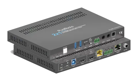
PT-HDBT-1021KVM-TX
2x1 18Gbps HDBaseT 3.0 Collaboration Transmitter
The PT-HDBT-1021KVM-TX is a 2x1 HDBaseT 3.0 collaboration transmitter with HDMI and USB-C inputs, supporting uncompressed HDMI 2.0 signals up to 4K 60Hz (4:4:4) over HDBaseT cabling for distances of up to 40m at 4K 60Hz …
ManualControl (TCP/IP)FAQSpecificationsDatasheetCEAvailable control interfaces. Expand an active type to see the full command table.
No matching commands.
RS-232 Commands27 commandsActive
ConnectionCommunication protocol: RS232 Communication Protocol Baud rate: 9600 Data bit: 8 Stop bit: 1 Parity bit: none↓ CSV
Source: manual, chapter RS232 Control, page 24
| Command | Description | Response | |
|---|---|---|---|
| STA. | Report system status. | PT-HDBT-1021KVM-TX 2x1 18G KVM Extender over HDBaseT 3.0 FW Version: V1.0.0a Power On! Front Panel Unlock! Local RS232 Baudrate Is 9600! MAC:50-2E-AB-0C-DE-7C! GUI IP DHCP:OFF! GUI_IP:192.168.0.178! GUI_SM:255.255.255.0! GUI_GW:192.168.0.1! HDMI Out Switch Auto Mode! HDMI Out Switch To 01! Input 01 EDID From 03 EDID! Input 02 EDID From 03 EDID! Out HDCP Follow Output! Tx Loopout Down Scale On! Trigger Mode Is 5V! Audio De-embedding On! Device Power Mode Is Follow Host! | |
| RST. | Factory reset. | Factory Default! | |
| Baudrate[x]. | Set baud rate to [x]. [x] can be 2400, 4800, 9600, 19200, 38400, 57600, or 115200. Example: Baudrate9600. | Set Local RS232 Baudrate To 9600! | |
| POWON. | Power on system. | Power On! | |
| POWOFF. | System standby. | Power Off! | |
| HDMI[X]. | Select X as the video input source. [X] can be 1-2. | HDMI Out Switch To 01! | |
| HDMIA. | Enable Auto-Switch Mode. | HDMI Out Switch Auto Mode! | |
| HDMIM. | Enable Manual Switch Mode. | HDMI Out Switch Manual Mode! | |
| AOUTON. | Turn on the audio de-embedding. | Audio De-embedding On! | |
| AOUTOFF. | Turn off the audio de-embedding. | Audio De-embedding Off! | |
| EDID/[XX]/[YY]. | Render the video source that connected to the [xx] port on the transmitter to use the EDID of [yy]. [XX] represents the video input port. 00: represents all the input ports. 01: represents No. 1 video input port. 02: represents No. 2 video input port. [YY] represents the included EDID as below: 01: Use the EDID of the screen that connect to the transmitter (TX). 02: Use the EDID of the screen that connected to the receiver (RX). 03:1920x1080@60 8bit Stereo (default) 04:1920x1080@60 8bit High Definition Audio 05:3840x2160@30Hz 8bit Stereo Audio 06:3840x2160@30Hz Deep Color High Definition Audio | Example: EDID/01/01. Feedback: Input 01 EDID Upgrade OK By 01 EDID! | |
| EDIDUpgrade[xx]. | The serial port upgrades EDID data. [xx] represents the input port, the value can be 00, 01, 02, U1, U2, U3 and U4. [xx]=00-02 means to customize the EDID of the corresponding input port (EDID is switched to the custom EDID after customization, and will not be saved in the machine), 00 means to operate on all input ports, 01-02 means input 01-02. [xx]=U1-U4 means custom built-in EDID (can be saved in the machine and recalled at any time), only one built-in EDID can be customized, and the current EDID still used after the customization is completed will not switch to the customized EDID. After receiving the instruction, the machine will prompt to send the EDID file. The file format must be .bin within 10s (in order to ensure normal data reception, all Input XX/User Define EDID Upgrade OK!) | RS232 Control HDBaseT must be disconnected before sending the instruction). | |
| LOCK. | |||
| UNLOCK. | |||
| SetDevicePowerMode[XX]. | Set the power mode: XX = 00-01 00: Follow Host 01: Always On | Set Device Power Mode To Follow Host! Set Device Power Mode To Always On! | |
| SetGuiIP:xxx.xxx.xxx.xxx. | Example: SetGuiIP:192.168.0.18. | SETGUIIP:192.168.0.18! | |
| SetGuiIP_DHCPON. | |||
| SetGuiIP_DHCPOFF. | |||
| /+[X]:XXX. | Control the surrounding devices that connects to it. [X] represent the baud rate; it can be 1-7. 1—2400, 2—4800, 3—9600, 4—19200, 5—38400, 6—57600, 7—115200 XXX represents the ASCII code. | Example: /+3:123456. Feedback: 123456 | |
| SIGNALTRG[XX]MODE. | When setting the detection mode [xx] is 1, it is 5V detection. And when it is 2, it is TMDS detection. | Set Trigger Mode To 5V! | |
| DSON. | |||
| DSOFF. | |||
| CEC[I/O][port][command]. | [I/O]: represent either video input ports or video output port the command will be sent to. I: means the CEC command will be sent to video input port, which are the USB-C and VIDEO (HDMI port). Example: CECI010444A Feedback: CEC Input 01 Send Success! Example: CECO018004 CEC Output Port Details O: means the command will be sent to video output port, which are LOOPOUT (HDMI port) and the HDBT. [port]: specify the exact port of input/output to pass the command. When [I/O] is set to I, check the clarification if the [port] is set to below: 00: the command will be sent to both USB-C and VIDEO port. 02: the command will only be sent to the VIDEO port. When [I/O] is set to O, check the clarification if the [port] is set to below: 00: the command will be sent to LOOPOUT and HDBT. 01: the command will be sent to the display that connects to LOOPOUT port. 02: the command will be sent to the HDBT port, and finally will be send to the display that connects to the receiver remotely. [commands]: represents the exact CEC commands that need to be sent to. Please note, the CEC command must in hexadecimal format with a maximum length of 12 bytes. | Feedback: CEC Output 01 Send Success! | |
| HDCPPAS. | HDCP Details If the input has HDCP 2.2, the output will also have HDCP 2.2. If the input has HDCP 1.4, the output will have HDCP 1.4. If the input does not have HDCP, the output will not either. | ||
| HDCPMAT. | HDCPACT. Render the HDCP of the output follows the input. If the input has HDCP, no matter which version it is, the output will have HDCP 1.4. If the input does not have HDCP, the output will not either. | HDCP Active! | |
| HDCPOFF. | Turn off the HDCP of output. If it is turned off, there will not be any HDCP on the video output, regardless of whether the video input has HDCP or not. | Out HDCP DBG OFF! | |
| SETMAC:AA-BB-CC-DD-EE-FF | Example: SETMAC:01-02-03-04-05-06 | MAC:01-02-03-04-05-06! |