
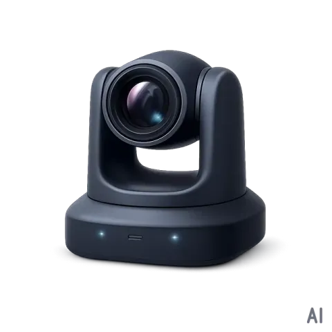
Introduction
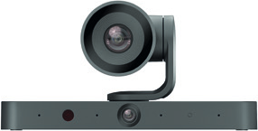
This product is a 4K optical binocular camera with a main lens that boasts a 4K optical zoom capability and a fixed lens captures in 1080P. Integrated with four linear array microphones, it enables precise sound source localisation, facilitating speaker tracking functionality. This product is designed to offer crisp image quality and an enhanced user experience in settings such as small to medium-sized conference rooms, training facilities, and online education environments.
Features
- 4K AI dual-lens optical camera that a 4K optical zoom capability, and a fixed lens captures in 1080P.
- Supports single screen output (from main lens) and dual-screen output (from main lens and panorama lens).
- 4x linear microphone arrays for sound source location.
- HDMI output supports a fixed 4K 30Hz resolution.
- Auto Framing / Speaker Tracking / Presenter Tracking / Individuals Gallery based on AI technology makes meetings more intimate and friendly.
- Supports PTZ function in AI tracking mode.
- Supports zoom function, 3x optical zoom in AI tracking modes, and 6x mixed zoom (3x optical zoom and 2x digital zoom) in manual mode.
- Supports IR remote control and LAN control (telnet API & Web UI).
- Compatible with multiple operation system, including Windows 10/11, Mac OS 10.10 or above.
- Support DC 12V or PoE / PoE+ (802.3at)
Package Contents
- 1x Camera
- 1x DC 12V 3A Power Adapter with US EU UK AU Pins
- 1x 1.8m USB-A to USB-C Cable
- 1x IR Remote
- 1x Private Lens Cap
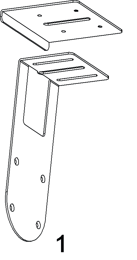
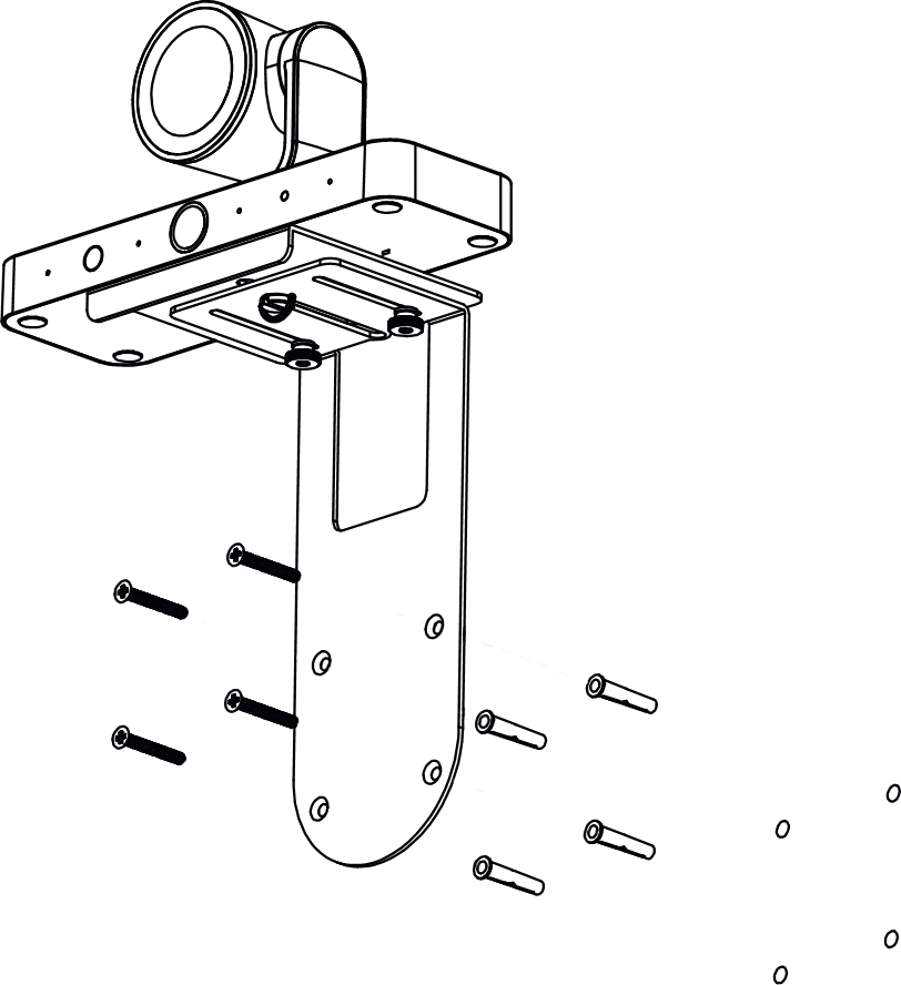
- 1x Base Bracket Panel (L 100mm x W 100mm x H 13mm)
- 1x Base Support Bracket (L 70mm x W 80mm x H 202mm)
- 2x M4 Blind Knob Nuts
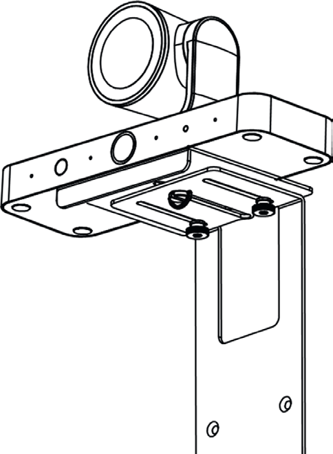
- 1x Thumb Screw (Stainless Steel)
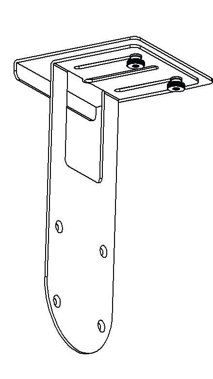
- 2x Bracket Assemble Screws (Cross-Recessed Countersunk Head Self-Tapping Screws, M4*L10)
- 4x Wall Mounting Screws (Countersunk Head Self-Tapping Screws, ø4x30, head diameter: ø7.2)
- 4x Rawl Plugs
Specifications
Video & Audio
| Input & Output Port | 1 x USB-C, 1 x HDMI OUT, 1 x USB-A, 1 x DC 12V IN |
|---|---|
| USB | USB 3.0/2.0 |
| Resolution Supported | MJPEG/H.265/H.264: 320x240@30fps, 640x340@30fps, 1280x720@30fps (default), 1920x1080@30fps, 3840x2160@30fps NV12: 320x240@30fps, 640x340@30fps, 1280x720@30fps (default)*, 1920*1080@30fps* |
| Note | The resolution above is only available for the main lens, and the resolution of the panorama lens is fixed 1080P@30fps, MJPEG. “*” indicates the resolutions aren’t supported by USB 2.0. |
| Output Video Encoding | MJPEG / H.264/H.265 / NV12 |
| USB Protocol | UVC 1.1 |
Camera
| Lens | Main Lens: 8MP, 3x optical zoom, DFOV: 110° Panoramic Lens: 2MP, fixed focus, DFOV: 120° |
|---|---|
| Sensor | Main Lens: 8MP Panoramic Lens: 2MP |
| White Balance | Auto |
| Backlight Compensation | Auto |
| Digital Noise Reduction | 2D, 3D Digital noise reduction supported |
| PTZ | Horizontal: ±75° Vertical: ±35° |
| HDR | Supported |
| Tracking Modes | Auto Framing / Speaker Tracking / Presenter Tracking / Individuals Gallery |
| Zoom Modes | Auto Framing / Speaker Tracking / Presenter Tracking / Individuals Gallery Mode (max. 3x optical zoom) Manual Mode: 6x mixed zoom, including 3x optical zoom and 2x digital zoom |
Speakerphone
| Microphone | 4x linear microphone arrays for sound source location |
|---|---|
| Peripherals | Support connecting with USB peripherals, such as Speakerphone or other third-party audio devices |
Communication and Control
| Compatible OS | Windows 10/11, Mac OS 10.10 or above |
|---|---|
| HDMI OUT | HDMI 1.4b with 4K 30Hz (no-HDCP) |
| Note | The HDMI OUT port continuously outputs signal unless the device is powered off or enters standby mode. |
| USB-C | USB-C 3.0 female connector (Compatible with USB 2.0) |
| Control Method | IR Remote, LAN (Telnet & Web UI) |
General
| Operating Temperature | 0°C ~ 40°C (32°F to 104°F), 10% to 90%, non-condensing |
|---|---|
| Storage Temperature | -20°C ~ 60°C (-4°F to 140°F), 10% to 90%, non-condensing |
| Power Supply | DC12V, 3A |
| Power Consumption | 10.824W (Max) |
| PoE | PoE / PoE+ (802.3at) |
| Dimension (Width x Height x Depth) | 200mm x 100.44mm x 69mm 7.87” x 3.95” x 2.72” |
| Net Weight | 0.44kg / 0.97lb |
Panel Description
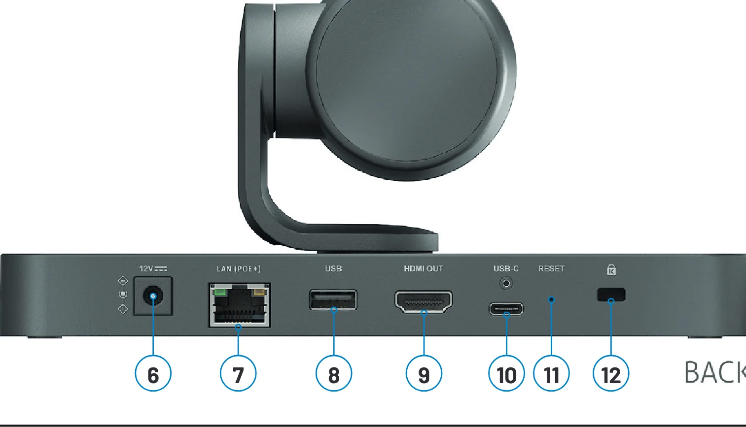
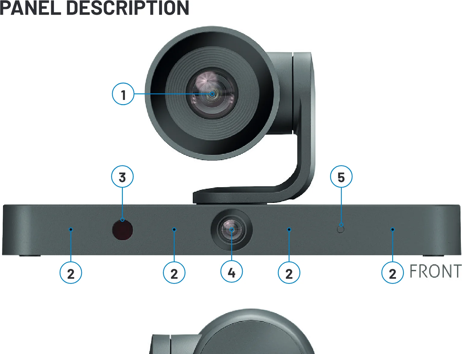
- Lens 4K optical zoom lens.
- MIC 4x linear mic arrays for sound source location.
- IR Window Receive IR signals from the provided IR remote.
- Lens 1080P fixed focus lens.
- Status LED • Lighting white for about 2s, and then off: The device is starting up. • Blinking dark white like breathing: The device is in idle mode, and the colour can set to red or off through web UI. • Lighting white: The device is active. • Blinking quickly: The device is being upgraded.
- DC 12V Connect to the provided power adapter.
- LAN Network control (web UI / telnet) plus PoE power
- USB USB 2.0 Type-A port. Connect to USB peripherals, such as speakerphone.
- HDMI OUT Connect to an HDMI display, video conference system, projector, or video capture.
- TYPE-C USB 3.0 Type-C port. Connect to a laptop, room PC or all-in-one conference device for transmitting audio and camera video signal using the USB-A to USB-C cable provided.
- RESET • Press once to show IP address and tracking mode on the connected display. • Hold and press for at least 10s to set the device to factory defaults.
- Kensington security slot.
Installation
Note: Before installation, please ensure the device is disconnected from the power source. Assemble the camera and mounting brackets:
- Assemble the base bracket panel and base support bracket using the two bracket assemble screws provided. As shown in the following figures:
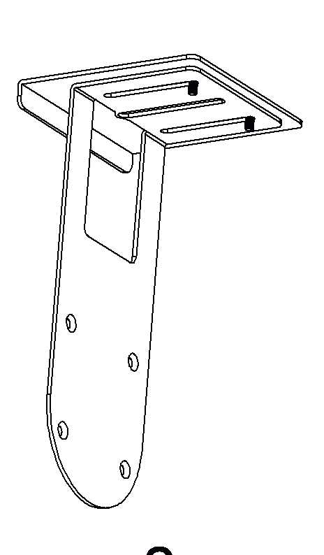
- Using the thumb screw to fix the mounting brackets to the camera, as shown in the figure.
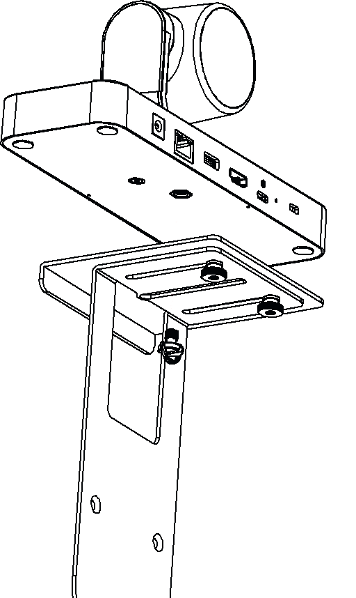
Note: If users want to install the camera on the wall, please assemble the base support bracket as shown in the following diagram.
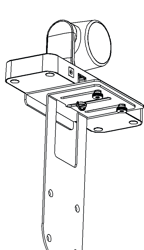
To install the camera on the TV:
- Loosen the two bracket assemble screws on the base support bracket, move the long baffle of the base support bracket to increase the distance between the two baffles.
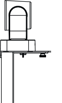
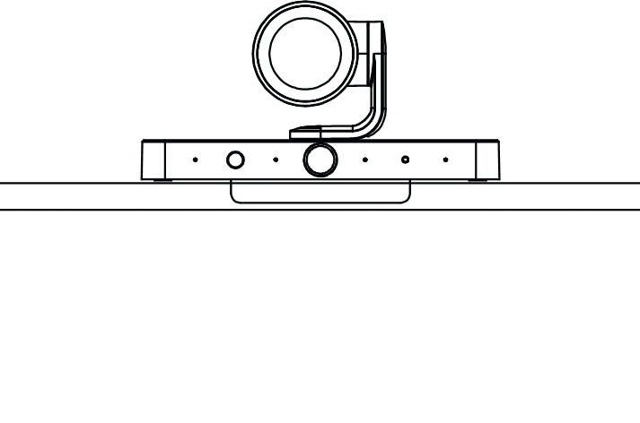
- Place the camera on the TV, move forward and backward to adjust the distance between the two baffles to adapt to the width of different TVs. As shown in the following diagram.
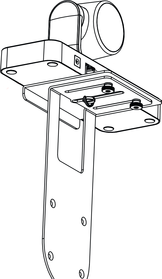
To install the device on the wall:
- Drill holes on the wall, then insert the rawl plugs into the holes.
- Using the provided wall mounting screws to install the camera on the wall. As shown below:
Typical Applications
Room PC
USB-A to USB-C
HDMI
Display
Camera
The camera supports three modes:
- Boot mode: At power on, the camera is in Boot mode. When there’s no UVC signal transmission and no HDMI display is connected with HDMI OUT port of the camera in 10s after starting up, the camera will enter idle mode. When the UVC channel is opened up, or the HDMI OUT is connected to the TV in 10s after starting up, the camera will enter active mode.
- Idle mode: In this mode, insert USB cable, or press any button of the IR remote, the camera will enter Init mode, and open up the UVC channel, the camera will enter active mode.
- Active mode: Turn off the UVC channel in this mode, the camera will enter Init mode, and in 10s, if there’s no UVC signal transmission and no HDMI display is connected with HDMI OUT port, the camera will enter idle mode.
Note: The camera supports receive commands from UVC channel through AI mode, IR remote, web UI or other third-party apps such as zoom.If an external cascade speakerphone is connected, the cascade device only transmits audio. In this case, the MIC and SPK of this cascade device can be displayed in the UC App’s menu and remain in working state, regardless of whether the current VL-PTZ100P is active.Good system design and engineering practices lead to PoE+ being highly recommended. However, if prior equipment or budget dictate using a PoE switch, please test and verify that the switch’s PoE capability will work with VL-PTZ100P.
IR Remote Control
The camera supports IR remote control. Point the provided IR remote to the IR window on front panel of the camera.
Button Description
| Button | Description |
|---|---|
| AI tracking | Press button to switch between: Auto Framing / Speaker Tracking / Presenter tracking / Individuals Gallery / Off |
| Standby | Short press for standby mode. |
| Home | Press once to return to the default angle when tracking is off. Press and hold to display OSD information (Tracking Mode and IP Address). |
| Navigation | When AI tracking is off, you can manually pan and tilt the PTZ lens. |
| Preset Position | When tracking mode is off, move to the target position. Press and hold the button for 3 seconds to save it as a preset position. |
| Zoom in/out | When AI tracking is off, use the following controls: ‘+’ button: Zoom in ‘-’ button: Zoom out |
Tracking Mode Introduction
- Off: Users can adjust the focal length to zoom in or out of the scene by pressing the navigation buttons. To pan the camera view up, down, left, or right, press the respective arrow buttons on the remote panel.
- Auto Framing: The optical AI lens will monitor in real-time the positional changes of individuals in the meeting venue, automatically adjusting angles and focal lengths to ensure that the target person is framed while maintaining optimal clarity of their facial features.
- Speaker Tracking: The camera will locate the speaker according to their voice, automatically select and frame the speaker (left/right: ±15°), providing a close-up view.
- Presenter Tracking: The camera automatically identifies the first speaker and continuously tracks the presenter in real-time.
- Individuals Gallery: The camera will identify and automatically frame each individual presenter within the meeting space, and displayed in horizontal split screen on the image, thereby enabling remote participants to clearly observe the facial expressions and body language of every attendee. In scenarios where the number of participants exceeds four, the camera will seamlessly transition to an Auto Framing mode.
Note: It is recommended that the distance between the camera and the participants does not exceed 6m.
Web UI introduction
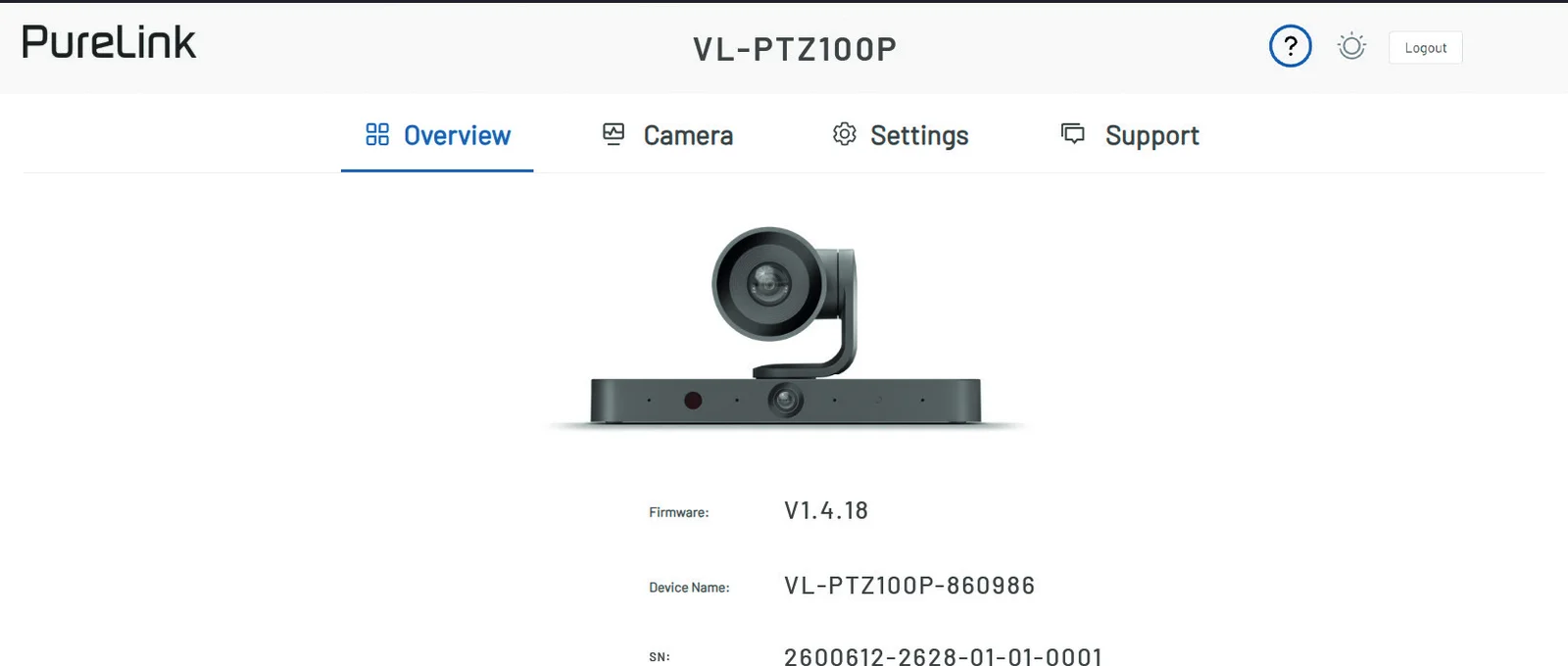
- Overview This section shows the device’s firmware version and device name.
- Camera This section allows users to control the camera. Preview Button: Click to start preview mode, where the video feed from the camera will be displayed in this frame for real-time preview (note that the camera will be unavailable for use in other software during preview). All settings will be reflected live in this view. To exit preview mode, simply move the mouse to the center of the screen and click the black square.
- Tracking Mode: Click to select a tracking mode from the drop-down menu, the tracking modes includes:
- Auto Framing
- Presenter Tracking
- Speaker Tracking
- Individuals Gallery
- Off
- When Tracking Mode is off, users can adjust the focal length to zoom in or out of the scene by moving the circular slider. To pan the camera view up, down, left, or right, click the respective arrow keys on the left side.
- To pan the camera view up, down, left, or right, click the respective arrow keys on the left side.
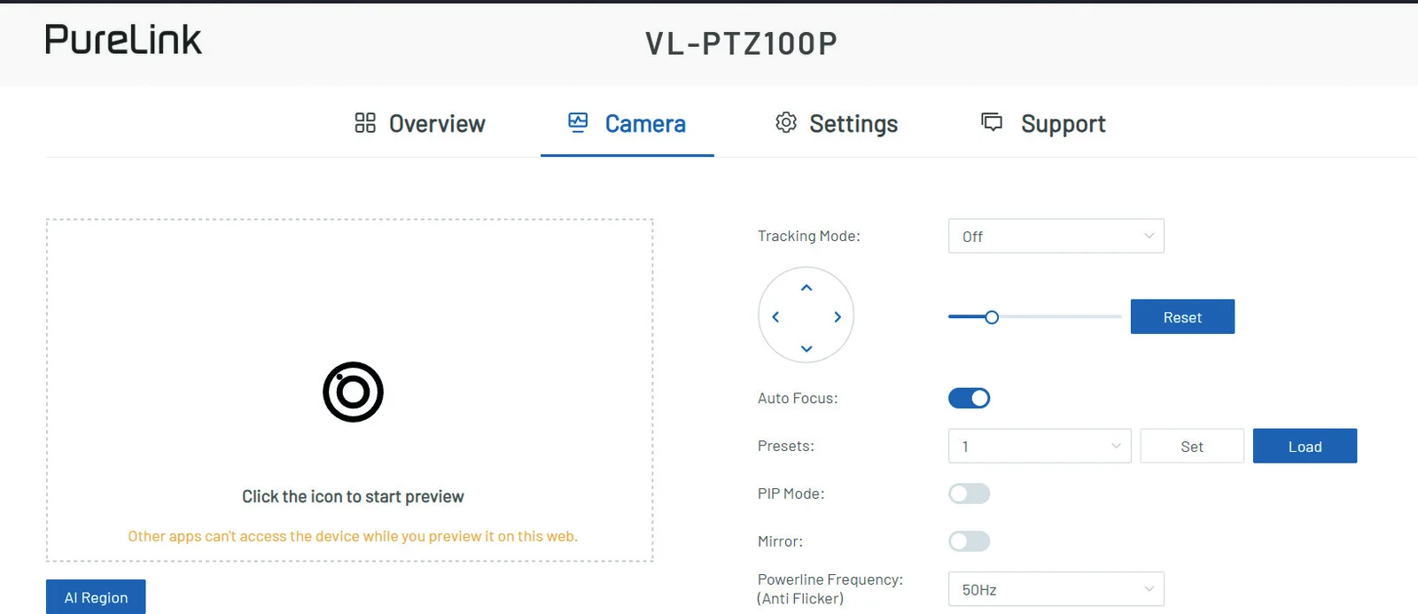
- Reset: Click the button to reset the focal length to default setting.
- Preset: Select a preset number and click “Set” to save current camera view to this preset. Click “Load” to upload the saved camera view from the selected preset.
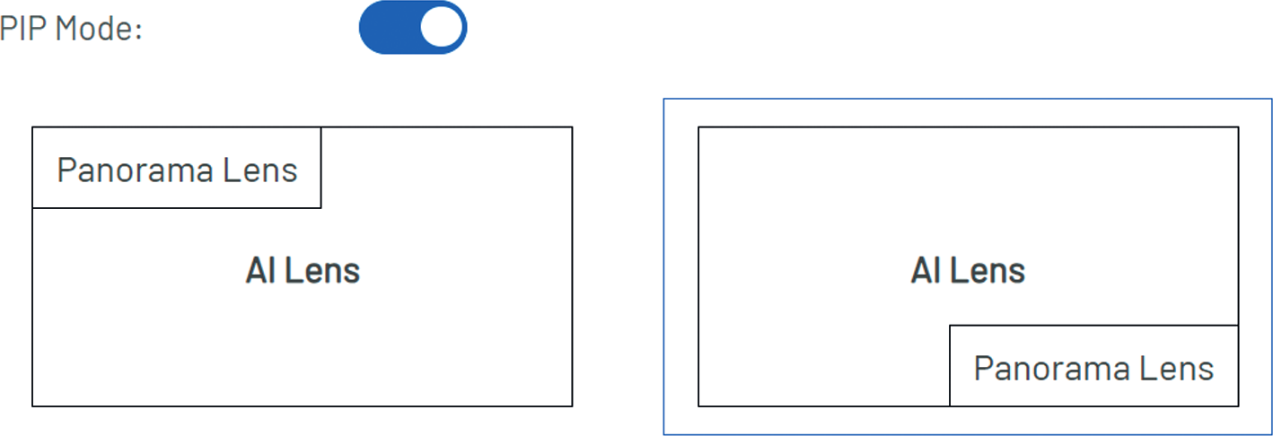
- PIP Mode: Click to set PIP mode to on/off. The default setting is off. When set it to on, users can select PIP layout mode through click the corresponding layout diagram. The default layout: the Panorama lens screen is on the lower right corner of the AI lens screen.
- When Tracking Mode is set to Auto Framing (default): The optical AI lens will monitor in real-time the positional changes of individuals in the meeting venue, automatically adjusting angles and focal lengths to ensure that the target person is framed while maintaining optimal clarity of their facial features.
- Tracking speed: Select tracking speed from the drop-down menu. The camera supports three tracking speed, Fast, Normal, and Slow. The default setting is Fast.
- When Tracking Mode is set to Speaker Tracking: The camera will locate the speaker according to their voice, automatically select and frame the speaker (left/right: ±15°), providing a close-up view.
- PIP Mode: The settings are the same as when tracking mode is set to off.
- When Tracking Mode is set to Presenter Tracking: Automatically identifies the first speaker and continuously tracks the presenter in real-time.
- PIP Mode: The settings are the same as when tracking mode is set to off.
- When Tracking Mode is set to Individuals Gallery: The camera will identify and automatically frame each individual presenter within the meeting space, and displayed in horizontal split screen on the image, thereby enabling remote participants to clearly observe the facial expressions and body language of every attendee. In scenarios where the number of participants exceeds four, the camera will seamlessly transition to an Auto Framing mode.
Note: It is recommended that the distance between the camera and the participants does not exceed 6m.
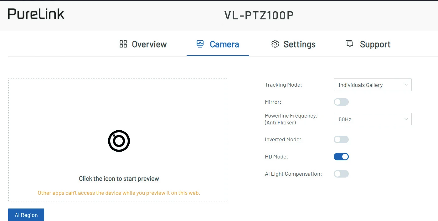
- Mirror: Click to set the camera’s mirror display function to on/off. The default setting is off.
- Powerline Frequency: Set the camera‘s AC frequency (50Hz or 60Hz, default 50Hz) to match the corresponding environment‘s frequency, to prevent flickering during recording.
- Inverted Mode: Click to set the inverted mode to on/off. The default setting is off. When it is set to on, the camera‘s display will be upside down.
- HD Mode: Click to turn on or off the high-definition camera view (default is on). The state change will automatically restart the device to apply the setting. To ensure better compatibility, users may try turning this feature off. HD off: Resolution range is set from 320p up to 2160p. HD on: Resolution range is set from 720p up to 2160p.
Note: The device name’s length must be 1-20 characters (letters, numbers, “_” or “-“ only).
Settings
- General Settings
- Device Name: This section allows users set device name and room name. Input the names and click “Apply” to take effect.
- IP Settings: This section is used to set between the static and dynamic IP address.
- DHCP: When enabled, the IP address of the camera is assigned automatically by the DHCP server connected.
- Static: When enabled, set up the IP address manually.
- Apply: Click to enable the network setting.
Note: When „Static“ is selected, please ensure your PC is in the same network segment as the camera.Please wait for 2-3 minutes for the camera‘s LAN module to reboot and reconnect after the network setting is changed.
- IP Conflict Detection: This section allows users to set IP conflict detection function to turn on/off. The default setting is on.
- HDMI Output Controls whether the camera transmits video through its HDMI port. Default: enabled.
- Enabled: The camera outputs video normally through the HDMI interface.
- Disabled: Video transmission through the HDMI port is stopped while other camera functions remain operational.
- Standby Indicator: Sets the status LED colour in idle mode. Default: White breathing.
- Privacy Position: Moves the camera lens to a predefined orientation away from the meeting area, so the room and participants are not visible - for temporary privacy during a meeting or presentation. The camera stays powered and connected; only video capture of the space is restricted.
- NDI Settings: This section allows users to enable / disable NDI output, and configure main stream and preview stream parameters.
LAN Control
- Telnet Control Connect a control PC to the LAN port of the device. Before you intend to control the device through telnet API, users shall establish connection between this device and your computer. The form of the command for telnet connection is below:
- telnet IP (Port)
- IP: The device’s IP address. Port: The device’s port number, this is non-required for some telnet control tools. Default setting is 23.
- For example, if the device’s IP address is 192.168.11.143, the command for telnet connection shall be the following:
- [object Object]
- Web UI Control The Web UI designed for the device can be accessed through a browser with latest version, e.g., Chrome, Safari, Firefox, Opera, IE10+, etc. The default IP mode of the matrix is DHCP. Default login is:
- [object Object]
The Fallback IP address is: 169.254.1.100
- Connect the LAN port of the device to the Ethernet switch with DHCP server, and connect the PC to the same Ethernet switch.
- Get the IP address through pressing the home button of the provided IR remote (see “ IR Remote Control” section to get detail information) or press reset button on front panel of the device (see “Panel Description” section to get detail information).
- Input the IP address obtained in the last step in the browser and press “Enter” key on keyboard. The following page can be access in:
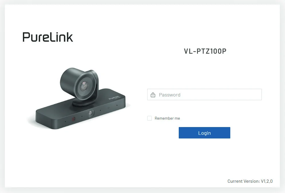
- Input the username and password to login the web UI. Both the default user name and password are “admin”.
- When login web UI first time, after clicking “Login”, users will enter the following window to change login password. Input new password and click “Apply” to enter the main page.
Note: The length of the password must be 4-16 characters in length (alphanumeric only).
- NDI OUT: Click to enable or disable. Default setting: OFF.
- NDI Name:
- Group Name: Input a group name and click “Apply” to take effect. Default: Public.
- Device Name: Input a device name and click “Apply” to take effect. Default: VL-PTZ100P-xxxxxx-TX
- Channel ID: Input a channel ID. Default value: 1.
- Main Stream / Preview Stream: Set parameters of main stream / preview stream.
- Encoder: Click the check box before H.264 and H.265 to select encoder of the main stream. Default setting: H.264.
- Resolution: Available resolutions depend on Low Latency Mode (General Settings). Disabled: NDI output maxes at 4K@30 with no preview stream - enabling preview shows the OSD message „Main stream resolution is 3840 x 2160@30fps, and preview stream transmission is not currently supported“; below 4K@30, preview is fixed at 640×360@30. Enabled: the main stream‘s NDI output is fixed at 1080p@60, with the preview stream again fixed at 640×360@30.
- I-Frame Interval: Input an I-frame interval. The number of frames between two consecutive I-frames, the range is 1~150.
- Bitrate Control: Click the check box to select bitrate control mode, CBR or VBR. Default setting: CBR.
- Bitrate (Kbps): Input a bitrate rate. The main stream bitrate should be in the range 64-16384, and the preview stream bitrate should be in the range 64-4096.
Note: Maximum 64 characters. Allowed characters include letters, numbers, underscores („_“), hyphens („-“), and spaces. The first and last character must be a letter or number.
- Xyte Cloud: This section allows users to connect the device to Xyte Cloud and check the connection status. Xyte Cloud is a centralised platform for remote monitoring, management, and support of connected devices.
- System Settings
- Login: This section allows users to change login password. The default password is “admin”.
- Connect to Cloud: Enables or disables the connection to Xyte Cloud. Default: Off.
- Cloud Server Status: Shows the connection status of the Xyte Cloud Server; click the reload icon to retry.
- For more information on Xyte Cloud, visit www.xyte.ai
Note: The length of the password must be 4-16 characters in length (alphanumeric only).
- Configuration: To copy a configuration for use in another installation, simply press the Export button, save the file and then import it into the new device; then hit Apply & Reboot to ensure the settings are saved.
- System: This section allows users to set the camera to factory defaults, reboot the camera and export log.
- Factory Reset: Click to set the device to factory defaults. Please wait 40s to re-access Web UI by refreshing the browser.
- Reboot: Click to reboot the device. Please wait 40s to re-access Web UI by refreshing the browser.
- Export log: Click to export the log file to local PC.
Support
Device Information
This section shows the device’s information, including device model, current version and build time. Move the mouse to the icon in Current Version line, it will show the version of each module.
- Firmware Update
- This section allows users to upgrade firmware. Click “Select the firmware files” bar to upload the upgrade file with latest version from local PC, and then click “Upgrade & Reboot” to upgrade firmware. When the upgrade completes, the device will automatically reboot.
Note: Do not unplug the device during upgrading process.
- Support
- This section allows users to download support documentation.
Warranty and liability
If any fault or damage is detected on your product, please contact your dealer and provide your sales slip or invoice as evidence of the purchase, if necessary. Your dealer will repair the fault either on site, or send the device to PureLink.
Please describe the possible faults in detail - only then you can be assured that faults, occurring only rarely, will be found and repaired with certainty! Any use other than described in this users manual is not permitted.
Disclaimer of liability
PureLink GmbH will not be held liable, nor provide any warranty for damage resulting from improper installation, assembly and use of the product, or failure to observe the operating instructions and/or safety instructions.
Trademark
Product model and logo are trademarks. All other trademarks mentioned in this manual are acknowledged as the property of the trademark owners. No part of this publication may be copied or reproduced without prior written permission of their respective owners.
CE Conformity
PureLink GmbH hereby declares that this product is in compliance with the essential requirements and other relevant provisions of the EMC Directive 2014/30/EU and the RoHS Directive 2011/65/EU amended by 2015/863 EU. PureLink GmbH hereby declares that this product is in compliance with the essential requirements of the applicable UK Regulations.
The EU Declaration of Conformity is available here: www.purelink.de
Disposal of device
WEEE-Reg.-Nr. DE 93847290
According to the European WEEE Directive, electrical and electronic equipment may not be disposed of with household waste. As a consumer, you are obliged to return electrical and electronic equipment free of charge at the end of its service life to the public collection points set up for this purpose or to the point of sale. Details on this are regulated by the respective national law. The symbol on the product, the instructions for use or the packaging refers to these regulations Recycling old appliances in this way is an important contribution to the protection of our environment.
Legal & Compliance
Product identification
Model: VL-PTZ100P – manual version 1.0
Batteries
Batteries must not be disposed of with household waste. Return used batteries free of charge to collection points or retailers.
Packaging
Dispose of packaging separately by material (paper/cardboard, plastics) via the local collection systems. Keep packaging material away from children – risk of suffocation. Packaging register LUCID: DE5958616449295.