
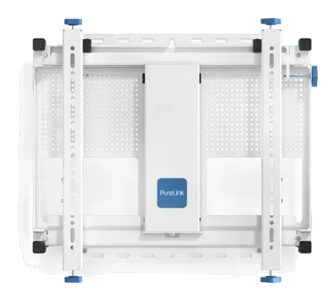
INSTALLATION SAFETY INSTRUCTIONS
This mount is intended for use with screens up to 40kg/88lbs. Exceeding this weight can result in instability causing damage or injury. Always use caution when installing.
Do not attempt to install this product until all instructions and warnings have been read and properly understood.
Please keep these instructions for future reference.
Please check carefully to make sure there are no missing or defective parts. Defective parts must never be used.
PureLink GmbH, its distributors and dealers are not liable or responsible for damage or injury caused by improper installation, improper use or failure to observe these safety instructions. In such cases, all guarantees will expire.
General
PureLink GmbH recommends that a professional AV installer or other suitably qualified persons, install this product.
Great care must always be taken during installation as AV equipment is fragile, possibly heavy and easily damaged.
If you do not fully understand the instructions or are not sure how to install this product safely, then please consult a professional for advice and/or to install this product for you. Failure to mount this product correctly may cause serious injury or death both during installation and at any time thereafter.
Do not mount any AV equipment that exceeds the specific weight limit of the product you are installing. This weight limit will be clearly stated on each product and its packaging and will vary from product to product.
Product location
Please pay careful attention to where this product is located. Check load capacity of wall prior to installation as some walls are not suitable for installation. Designed for indoor use, this mount is suitable for public or home installation.
If located in a public area, ensure the product is out of the immediate reach of people. If any AV equipment is to be suspended over the likely path or location of people, then great care must be used, ensuring all equipment is securely fixed to a wooden stud, concrete block or other permanent structure.
Installing on drywall boards alone will not support the weight of most AV equipment.
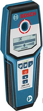
When drilling holes in walls it is essential to avoid contact with electrical cables, water or gas pipes, contained within. Use of a good quality live wire detector and hidden abscess locator is therefore recommended.
Only drill into structures when you are sure it is safe to do so.
Fixing hardware
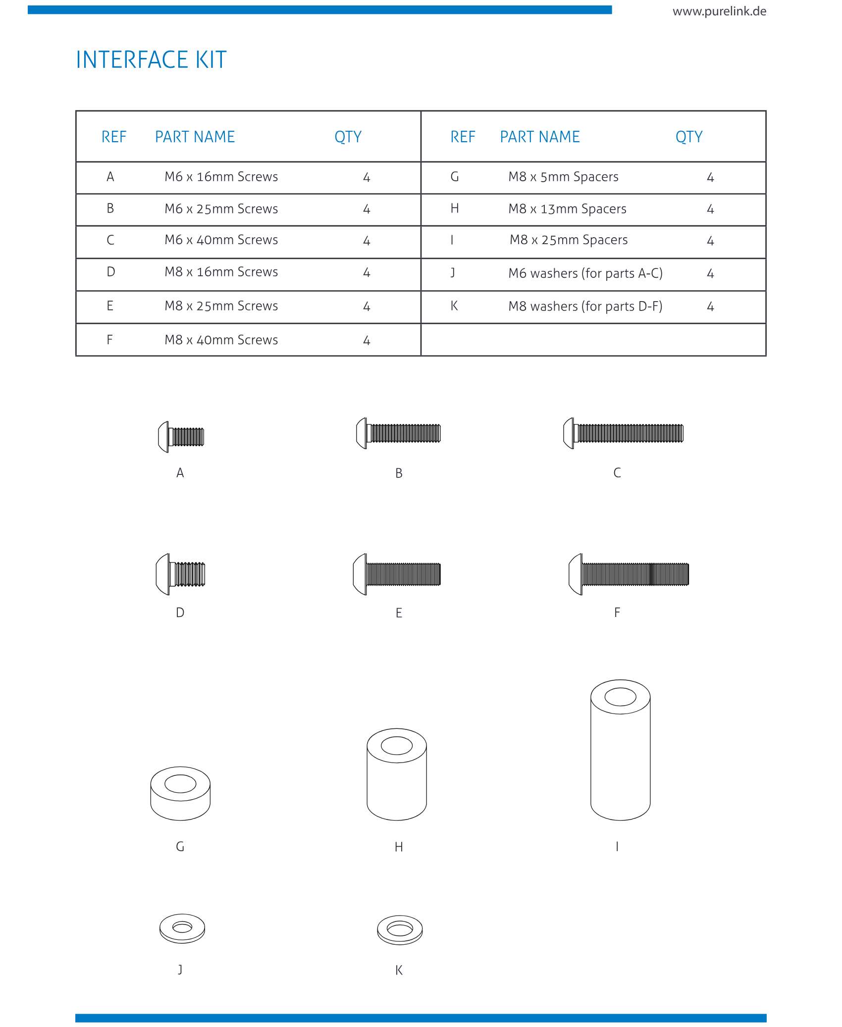
It is highly recommended that all wall fixings be used where supplied and that the purpose of all hardware is fully understood.
In some cases, more AV equipment fixing hardware will be supplied to accommodate different models of equipment and set up configurations.
The installer must be satisfied that any suapplied fixing hardware is suitable for each specific installation. If any fixing screws or included hardware are deemed not sufficient, for a safe installation, then please consult a professional or your local hardware store.
Hazard limitation
When routing cables take advantage of any built-in cable management features that the product might provide and ensure that all cables are properly routed and secure. Check to see that any moving aspect of the product can do so unhindered by any cabling. Do not block the sensor beam area of the No-Touch Mount.
Some products have moving parts and the potential to cause injury through the crushing or trapping of fingers or other body parts, exercise care and read all warnings.
Pay close attention to all moving parts, especially when assembling, installing and servicing. Immediately after installation, double check that the work done is safe and secure. Double check all necessary fixings are present and suitably tightened.
It is recommended that periodic inspections (not greater than 6 months apart) of the product and its fixing points are made, to ensure safety is maintained. If in doubt, consult a professional AV installer or other suitably qualified person.
General recommendations
Check the wall structure being mounted to. Use a level to ensure the wall is flat and note areas of concern. Use washers, shims or spacers between the wall and the mount to create a flat surface for mounting. A flat mount will make adjustments much easier and faster when aligning screens.
Note: The PureLink GmbH No-Touch Mount is ONLY suitable for installation perpendicular to the floor in portrait or landscape orientation. It is NOT suitable for angled or overhead mounting. For angled mounting please see Soft-Touch Mount on www.PureLink.de
We recommend video walls start in a corner, we show starting at the bottom left then add the screens row by row, aligning the screens as you build. Also, make sure depth and lateral micro adjustments are centered before installation, making alignment quicker and easier.
Note: Walls are built from different materials and require different wall bolts for best performance and safety. Please select suitable fixings or consult an expert for guidance.
- Start from the bottom corner of the video wall configuration.
- Height of screen determines center to center distance for next vertical mount location.
- Width of screen determines center to center distance for next horizontal mount location.
- Build Horizontallly first then add rows until all rows are completed.
- Align the two common borders before mounting the next screen
- Align the one common border before mounting the next screen
Height of screen + a gap
INSTALLATION INSTRUCTIONS
Step 1 Unpack and check all parts
Open top and bottom handwheels on Interface Arms (closed for shipment). Check depth and lateral adjustment knobs are centered in adjustment range.
- Open top and bottom Handwheels
- Control Box
- Interface Arms Extension Arms
- Keep area below control-box clear (light-beam)
- Center
Step 2 Measure, mark and drill holes
- Use level to check alignment.
- Use an Electric Wall Scanner to locate electrical wires to drill holes in the wall safely
- Tighten all wall bolts (5 pcs recommened).
Caution: Do not hang screen on mount (until step 7).
- Wall fixing holes
- Level
- Use minimum 2 wall bolts (3 recommended) at Top and 2 wall bolts bottom of mount. Heavier screen should have 3 bolts including center top keyhole location.
- Electric Wall Scanner
Step 3
Universal Controller
Connect the power supply to the control box and electrical socket. Only use the power supply provided. If not possible, contact us to ensure the appropriate replacement is used.
Caution: The use of 3rd party power supplies will void warranty!
Note: Once the screens are installed aligned and closed, to prevent accidental movement of the Mount or electrical interference/damage, ensure that Mount-dedicated power strips or power supply is turned off/unplugged, until next service appointment.
Connect the power supply to the control box
Step 4
The PureLink GmbH No-Touch Mount, allows the screen to move OUT and IN, without the need to touch the screen.
Position the control wand approximately 85mm (3 1/3”) to the right of center of the mount (see below). The mount will slowly start to move OUT.
85mm 3 1/3’’
How to use Universal Controller to operate the Mount
Move Universal Controller with the Mounts
Movement
Once the Universal Controller is positioned below the light beam, the Mount will start moving. To keep the Mount moving, make sure you follow this movement also with the Universal Controller. If you leave the light beam, the Mount will STOP.
To STOP the Mount, remove the Universal Controller from the light beam
The Mount will only move as long the Universal Controller is below the light beam. Once removed from light beam, the Mount will STOP
To CHANGE the Mounts DIRECTION, quickly SWIPE the Universal Controller through the light beam
- You will hear a signal:
- 2 beeps: move IN
- 3 beeps: move OUT
After hearing the signal, position the Universal Controller again below the light beam to move the Mount in the chosen direction.
When fully closed or open, it will not beep as it can only move one direction.
Installation, connectivity and product data
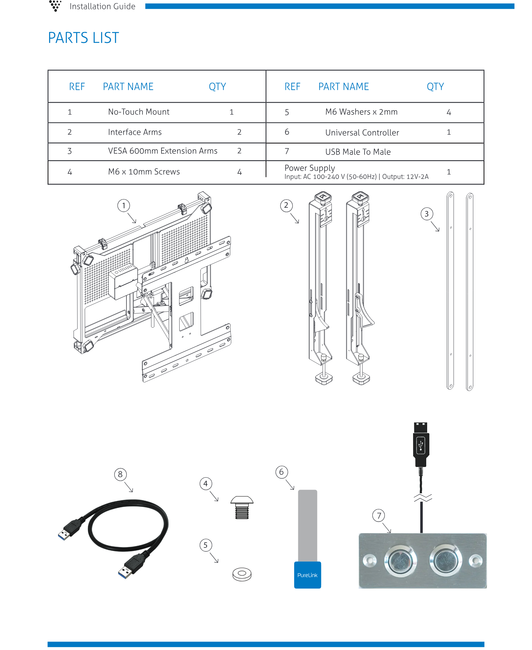
Attach the Interface Arms to the screen (Landscape or Portrait)
The interface arms fit from VESA 200 x 100mm through 400 x 400mm.
For 600 x 400mm or 400 x 600mm use supplied extension arms.
X Y
Z
Step 7 Make Adjustment
A : Height adjustment
B: Corner depth adjustment
C: Lateral macro adjust
D: Lateral micro adjustment
E: Locking handwheels (must be loosened for any adjustments)
Step 6
Connect screen to Mount
At slight angle, hook arms onto top of frame, then flatten screen onto Mount base until it clicks into position.
A
Height adjustment
B
Corner depth adjustment
C
D
Lateral Smart-Lock
1) unlock lateral Smart-Lock,
2) slide screen into position,
3) slide Smart-Lock to interface arm,
4) lock Smart-Lock.
1) After Smart-Lock is in position, the lateral micro adjustment can be used.
Lateral micro adjustment
Each time you add a screen to the video wall make needed adjustments.
Corner depth
Note: Locking handwheels must be loosened before any adjustments can be made.
Note: Once all adjustments are done, the locking handwheels can be tightened.
Height adjustment
Lateral Smart-Lock
Lateral micro adjustment
Tighten to secure (last step)
Corner depth
adjustment
D
E
Locking handwheels
RECESS FLAT SCREEN INSTALLATION
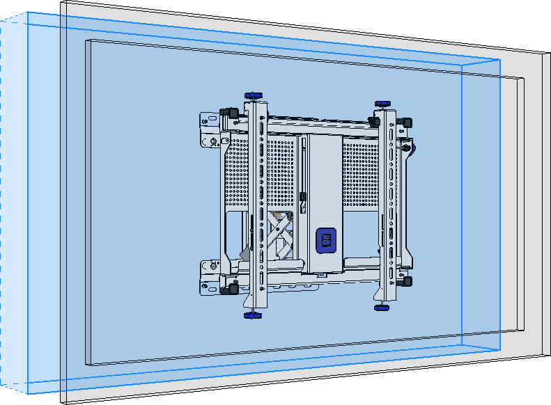
Step 1 Make a rectangular hole on the wall using the dimensions of the chosen screen by following the instructions below.
- Please ensure minimum gaps between the screen and four edges of the recessed box is 2mm and that corners and four angles are 90 degrees.
- Must use Electric Wall Scanner to locate the position of electric wires before drilling into the wall.
The hole on the wall (LxHxD)
L = Ls + X mm
H = Hs + Y mm
D = Ds + 100 mm
X, Y: Gap each corner
The mount
The screen (Ls x Hs x Ds)
Ls = Length
Hs = Height
Ds = Depth
The dimension of rectangular holes on the wall need to be created based on the screen’s dimensions.
Note: Some screen manufacturers do not put the VESA holes at the center of the screen backside. Therefore, you should locate the position of back wall plate and mark the drill holes with the following instruction.
Top of screen
Bottom of screen
Ls
Hs
Ds
H1
H3
H2
Y
X
Wall Hole
D
H
L
Center of wall hole
100
Mount space
Step 2 Locate the mount’s back wall plate by using tape ruler and bubble level.
Important: The VESA holes position of a monitor is pre-defined by the manufacturer.
- Must use Electric Wall Scanner to locate the position of electric wires before drilling into the wall.
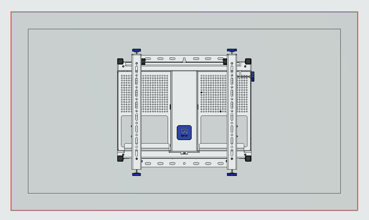
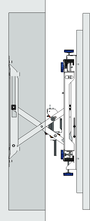
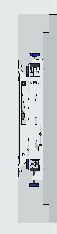
2.1 If H1=H3, the position of the mount will be in the middle of the recessed box (H1, H3: See on pages 15).
- Calculate and mark the retangular box for the position of back wall plate by 3 dimensions as bellow A1, A2, B (Size of back wall plate HxW=468.5x380 mm) => Use measuring tape to confirm 3 dimension A1, A2, B are right
- Put the mount on the wall hole and mark the drill holes
- Hang the screen and adjustment to fit with the wall hole (see pages 8-14).
Level
Top
Bottom
L
H
468.5 mm
380 mm
Center of wall hole
=Center of screen
Note: Use at least 2 wall bolts (3 recommended) at Top and 2 wall bolts bottom of mount. Heavier screen should have 3 bolts at the topMeasure, mark and drill holesUse level to check alignment.Use an Electric Wall Scanner to locate the electrical wire if you want to drill a hole in the wall.Tighten all wall bolts (6 pcs recommened).A1=(H-468.5)/2 mm
B=(L-380)/2 mm B=(L-380)/2 mm
A2=(H-468.5)/2 mm
Closed OpenedFront
Top
Note: The picture above show only back wall plate for easy understanding, in fact there will be the whole mount
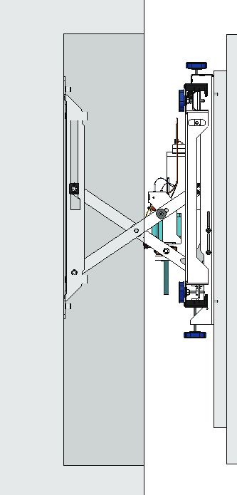
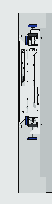
2.2 If H1<H3, the center of mount will be higher than the center of the recessed box.(H1, H3: See on pages 15).
Level
Top
Bottom
L
H
468.5 mm
380 mm
- Calculate and mark the retangular box for the position of back wall plate by 3 dimensions as bellow A1, A2, B (Size of back wall plate HxW=468.5x380 mm) => Use measuring tape to confi rm 3 dimension A1, A2, B are right
- Put the mount on the wall hole and mark the drill holes
- Hang the screen and adjustment to fit with the wall hole (see pages 8-14).
B=(L-380)/2 mm B=(L-380)/2 mm
Center of wall hole
Note: Use at least 2 wall bolts (3 recommended) at Top and 2 wall bolts bottom of mount. Heavier screen should have 3 bolts at the topMeasure, mark and drill holesUse level to check alignment.Use an Electric Wall Scanner to locate the electrical wire if you want to drill a hole in the wall.Tighten all wall bolts (6 pcs recommened).A1=(H-468.5)/2 - (H3-H1) mm
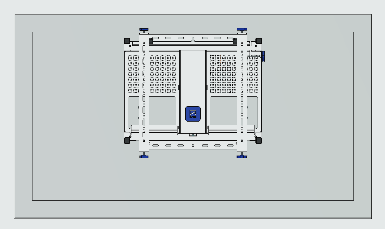
Closed OpenedFront
Top
Note: The picture above show only back wall plate for easy understanding, in fact there will be the whole mount
Center of screen
A2=(H-468.5)/2 + (H3-H1) mm
2.3 If H1<H3, the center of mount will be lower than the center of the recessed box.(H1, H3: See on pages 15).
- Calculate and mark the retangular box for the position of back wall plate by 3 dimensions as bellow A1, A2, B (Size of back wall plate HxW=468.5x480 mm) => Use measuring tape to confirm 3 dimension A1, A2, B are right
- Put the mount on the wall hole and mark the drill holes
- Hang the screen and adjustment to fit with the wall hole (see pages 8-14).
Note: Use at least 2 wall bolts (3 recommended) at Top and 2 wall bolts bottom of mount. Heavier screen should have 3 bolts at the topMeasure, mark and drill holesUse level to check alignment.Use an Electric Wall Scanner to locate the electrical wire if you want to drill a hole in the wall.Tighten all wall bolts (6 pcs recommened).
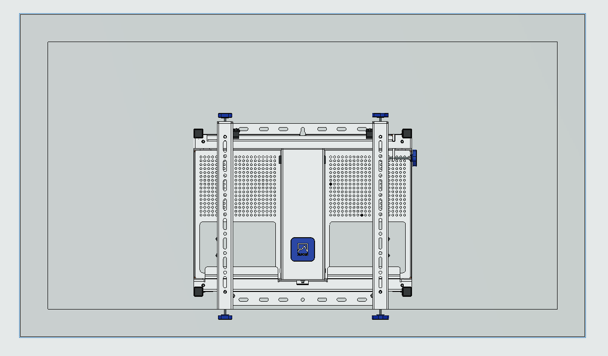
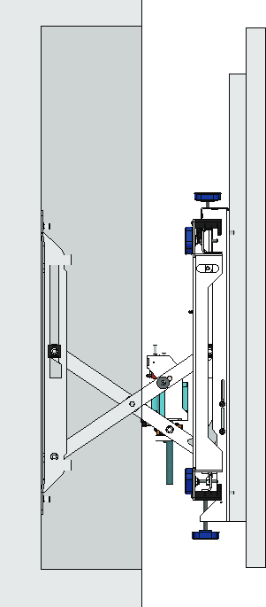
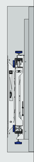
ClosedFront
Top
Opened
Note: The picture above show only back wall plate for easy understanding, in fact there will be the whole mount
Top
Bottom
L
H
468.5 mm
Center of wall hole
A1=(H-468.5)/2 + (H3-H1) mm
A2=(H-468.5)/2 - (H3-H1) mm
Level
380 mm
B=(L-380)/2 mm B=(L-380)/2 mm
Center of screen
CONNECTIVITY
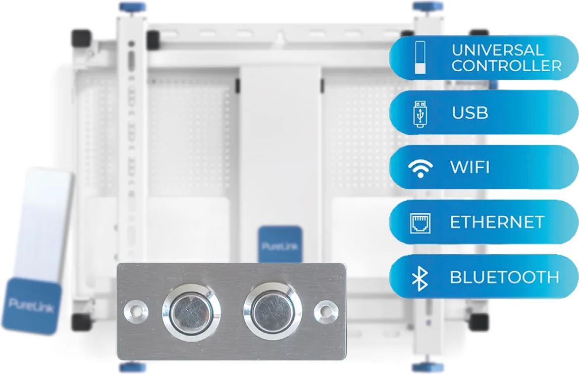
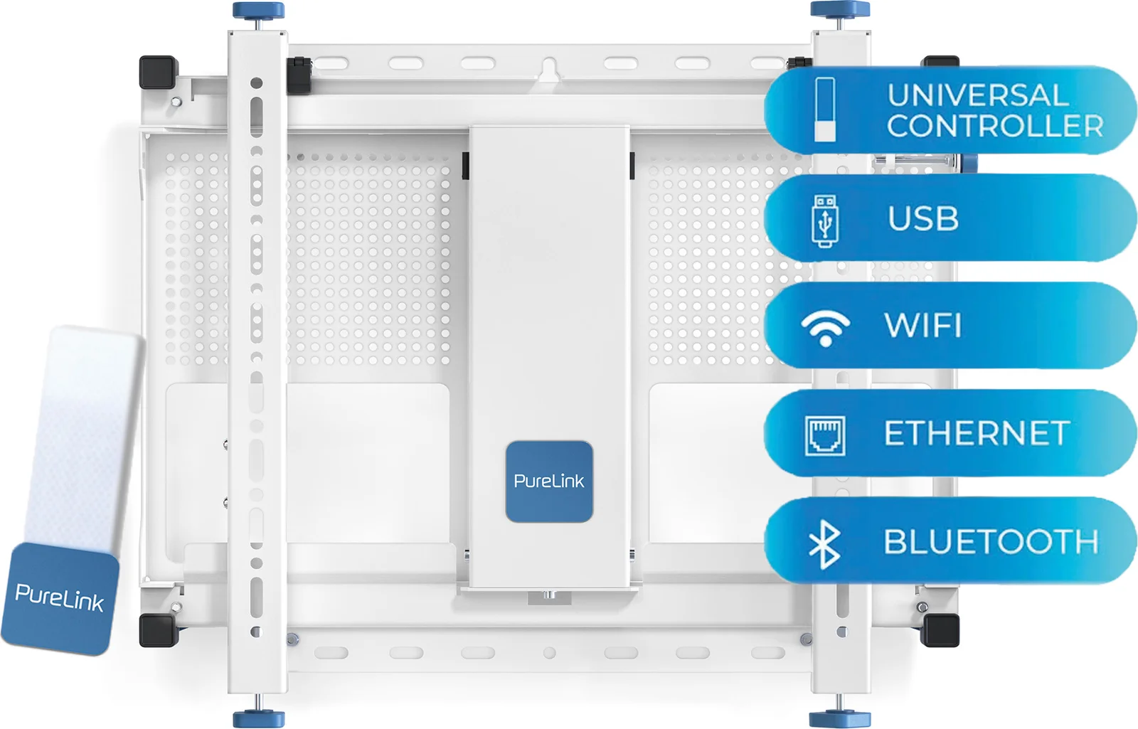
There are several different ways to control the mount
- Universal Controller
- USB
- Wifi
- Ethernet
- Bluetooth
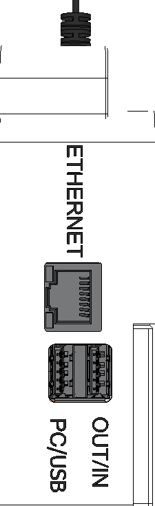
Control box
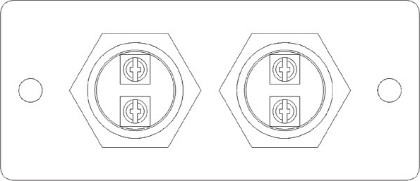
OUT/IN PORT
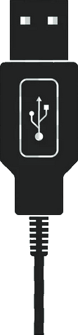
Secure the USB cable in place by tightening it to the
hole panel.
- Universal Controller To see how to control the mount using Universal Controller, go to pages 9-11.
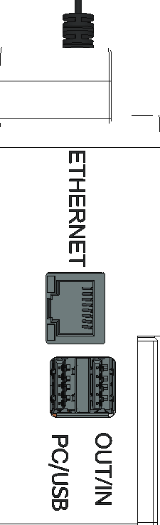
- USB There are 2 ways to control the mount via USB Port (USB button and PC via USB port)
- USB Button • Plug USB connector into the right position (OUT/IN) • Do cable management by using the hole panel • Press the buttom to move the screen out/in Important: • Don’t put the cable into the X-arm movement at center. • Secure the USB cable in place on both sides
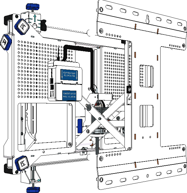
Note: How to wire the USB cable?
• Don’t use the 5V (Red) wire
WHITE
GREEN
GND (BLACK)
WHITE
GREEN
5V (RED), Don’t use red wire (Remove)
GND (BLACK)
IN OUT
PC via USB Port
- Plug one connector of the USB cable Male to Male to PC/USB port.
- Plug the other connector side to PC
Note: Don’t put the cable into the X-arm movement at center.
Secure the USB cable in place on both sides
Control box
PC/USB Port
USB Male-to-male cable
PC
Wifi
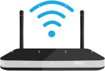
- The Mount connects to the Wireless Access Point via wireless connection.
- Wireless Access Point connects to the Internet Server.
- Laptop, PC or other devices connect to the Internet Server.
Caution: The Wireless Access Point needs to be as near the mount as possible
Control box
Mount 01 Mount 02
Control box
Wireless

Wireless Access point
INTERNET
LAPTOP PC DEVICES
SERVER
Need internet
Ethernet
Local Network Controller (Without internet)
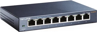
- The Mount connects to the Switch
- The Switch connects to computers/laptops.
Note: Secure the LAN cable in place by tightening it to the hole panel.
Control box
Mount 01 Mount 02
Control box
LAN cable LAN cable
LAN cable
Switch
PC
CONFIRMATION OF CE CONFORMITY
Disclaimer of Liability
PureLink GmbH will not be held liable, nor provide any warranty for damage resulting from improper installation, assembly and use of the product, or failure to observe the operating instructions and/or safety instructions.
PureLink GmbH hereby declares that the device type WM-NT400 is in conformity with the Directives 2014/30/EU, 2019/1782/EU, 2011/65/EU and 2015/863/EU.
WEEE-Reg. No.: DE 93 847 290
According to the European WEEE Directive, electrical and electronic equipment may not be disposed of with household waste. As a consumer, you are obliged to return electrical and electronic equipment free of charge at the end of its service life to the public collection points set up for this purpose or to the point of sale. Details on this are regulated by the respective national law.
The symbol on the product, the instructions for use or the packaging refers to these regulations Recycling old appliances in this way is an important contribution to the protection of our environment.
Self help guide
- Controller not remaining in correct location - if the Controller is on the edge of the light beam, as the controller moves forward and backward with the moving mount, it can move out of the beam and stop. Move the controller left and right to check the beam location. Also note, the beam moves forwards and backwards with the mount, so move controller as the screen moves.
- OR: Impact Detection is triggering. Impact detection exists but is variable depending on several factors including screen weight and size, where the impact occurs and if there is vibration. The motor will stop and when you place the controller back into the beam it will have reversed direction.
- When first started and if not run for some time the motor might automatically calibrate its location. This is normal and once it has gone through a full cycle it will resume normal operation.
- Check there is POWER. It is common to switch off or unplug power once set-up is finished, so check power is on. Check controller is in beam and move out of beam and back into beam.
- Are handwheels at base of screen arms loosened?
- If you are reaching the end of the range this will also occur. Make adjustments elsewhere to free up additional adjustment range.
Contact Us
PureLink GmbH
Von-Liebig-Str. 10 | 48432 Rheine
Germany
www.purelink.de | info@purelink.de
PureLink UK LTD.
Carpenter Court | 1 Maple Road | Bramhall
Stockport | Cheshire SK7 2DH
United Kingdom
Motor Starts then stops
Motor moves slowly
Motor does not start
Handwheels are hard to turn
Issues Solutions
PRODUCT DIMENSIONS
FRONT VIEW LANDSCAPE ADAPTOR
VESA 600mm X 400mm
FRONT VIEW PORTRAIT ADAPTOR
VESA 400mm X 600mm
| Dimension | Metric | Imperial | Tolerance |
|---|---|---|---|
| Width | 600mm | 23.6’’ | |
| Height | 400mm | 15.75’’ | |
| Other (width) | 600mm | 23.6’’ | |
| Other (height) | 400mm | 15.75’’ | |
| Other | 531mm | 20.9’’ | |
| Other | 574.5mm | 22.6’’ | |
| Other | 295mm | 9.8’’ | (+/-10mm) (+/-0.3) |
| Other | 100mm | 3.9’’ | (+/-10mm) (+/-0.3) |
PureLink GmbH | Von-Liebig-Str. 10 | 48432 Rheine | Germany | WEEE-Reg.-Nr. DE: 93847290
PureLink UK LTD. | Carpenter Court | 1 Maple Road | Bramhall | Stockport | Cheshire SK7 2DH | United Kingdom
Legal & Compliance
Product identification
Models: VL-WM-NT400, VL-WM-NT400W – manual version 1.0
Warranty and liability
The manufacturer grants the full statutory warranty on all new devices. As the manufacturer has no influence on installation, the warranty only applies to the product itself. If you detect a fault or damage, please contact your dealer and provide your sales slip or invoice as proof of purchase.
The manufacturer is not liable for damage to persons or property caused by improper installation, operation or maintenance not described in this manual. Do not alter or modify the product or its accessories. Any use other than described in this manual is not permitted and voids warranty and guarantee.
Packaging
Dispose of packaging separately by material (paper/cardboard, plastics) via the local collection systems. Keep packaging material away from children – risk of suffocation. Packaging register LUCID: DE5958616449295.