
Attivo
PT-HDBT-1021KVM-TX
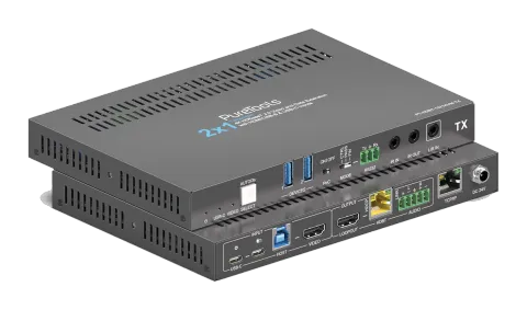
Trasmettitore di collaborazione HDBaseT 3.0 2x1 18 Gbps
Il PT-HDBT-1021KVM-TX è un Transmitter di collaborazione 2x1 HDBaseT 3.0 con ingressi HDMI e USB-C, che supporta segnali HDMI 2.0 non compressi fino a 4K 60Hz (4:4:4) su cablaggio HDBaseT per distanze fino a 40m a 4K …
ManualeComandi (TCP/IP)SpecificheScheda tecnicaCEInterfacce di controllo disponibili. Espanda un tipo attivo per visualizzare la tabella completa dei comandi.
Nessun comando corrispondente.
Comandi RS23227 comandiAttivo
Fonte: manuale, capitolo RS232 Control, pagina 24
| Comando | Descrizione | Esempio | Risposta | |
|---|---|---|---|---|
| STA. | Riporta lo stato del sistema. | PT-HDBT-1021KVM-TX 2x1 18G KVM Extender over HDBaseT 3.0 FW Version: V1.0.0a Power On! Front Panel Unlock! Local RS232 Baudrate Is 9600! MAC:50-2E-AB-0C-DE-7C! GUI IP DHCP:OFF! GUI_IP:192.168.0.178! GUI_SM:255.255.255.0! GUI_GW:192.168.0.1! HDMI Out Switch Auto Mode! HDMI Out Switch To 01! Input 01 EDID From 03 EDID! Input 02 EDID From 03 EDID! Out HDCP Follow Output! Tx Loopout Down Scale On! Trigger Mode Is 5V! Audio De-embedding On! Device Power Mode Is Follow Host! | ||
| RST. | Ripristino alle impostazioni di fabbrica. | Factory Default! | ||
| Baudrate[x]. | Imposta baud rate su [x]. [x] può essere 2400, 4800, 9600, 19200, 38400, 57600 o 115200. Esempio: Baudrate9600. | Set Local RS232 Baudrate To 9600! | ||
| POWON. | Accendi il sistema. | Power On! | ||
| POWOFF. | Sistema in standby. | Power Off! | ||
| HDMI[X]. | Seleziona X come sorgente video di input. [X] può essere 1-2. | HDMI Out Switch To 01! | ||
| HDMIA. | Abilita la modalità di commutazione automatica. | HDMI Out Switch Auto Mode! | ||
| HDMIM. | Abilita la modalità di commutazione manuale. | HDMI Out Switch Manual Mode! | ||
| AOUTON. | Accendi il de-embedding audio. | Audio De-embedding On! | ||
| AOUTOFF. | Spegni il de-embedding audio. | Audio De-embedding Off! | ||
| EDID/[XX]/[YY]. | Render the video source that connected to the [xx] port on the transmitter to use the EDID of [yy]. [XX] represents the video input port. 00: represents all the input ports. 01: represents No. 1 video input port. 02: represents No. 2 video input port. [YY] represents the included EDID as below: 01: Use the EDID of the screen that connect to the transmitter (TX). 02: Use the EDID of the screen that connected to the receiver (RX). 03:1920x1080@60 8bit Stereo (default) 04:1920x1080@60 8bit High Definition Audio 05:3840x2160@30Hz 8bit Stereo Audio 06:3840x2160@30Hz Deep Color High Definition Audio 07 | 3840x2160@60Hz 4:2:0 Deep Color Stereo Audio 08 | 3840x2160@60Hz Deep Color Stereo Audio 09 | 3840x2160@60Hz Deep Color High Definition Audio 10 | 3840x2160@60Hz Deep Color HDR LPCM 6CH 11 | User-defined EDID1 12 | User-defined EDID2 13 | User-defined EDID3 14 | User-defined EDID4 | EDID/01/01. | Input 01 EDID Upgrade OK By 01 EDID! | |
| EDIDUpgrade[xx]. | La porta seriale aggiorna i dati EDID. [xx] rappresenta la porta di ingresso, i valori possono essere 00, 01, 02, U1, U2, U3 e U4. [xx]=00-02 indica la personalizzazione dell'EDID della porta di ingresso corrispondente (l'EDID passa all'EDID personalizzato dopo la personalizzazione, e non sarà salvato nel dispositivo), 00 indica l'operazione su tutte le porte di ingresso, 01-02 indicano ingresso 01-02. [xx]=U1-U4 indica EDID incorporato personalizzato (può essere salvato nel dispositivo e richiamato in qualsiasi momento), è possibile personalizzare un solo EDID incorporato, e l'EDID attuale utilizzato dopo il completamento della personalizzazione non verrà cambiato all'EDID personalizzato. Dopo aver ricevuto il comando, il dispositivo chiederà l'invio del file EDID. Il formato del file deve essere .bin entro 10s (per garantire la normale ricezione dei dati, tutti Input XX/Aggiornamento EDID definito dall'utente OK!) | Input XX/User Define EDID Upgrade OK! | ||
| LOCK. | Lock front panel. | |||
| UNLOCK. | Unlock front panel. | |||
| SetDevicePowerMode[XX]. | Imposta la modalità di alimentazione: XX = 00-01 00: Segui Host 01: Sempre acceso | Set Device Power Mode To Follow Host! Set Device Power Mode To Always On! | ||
| SetGuiIP:xxx.xxx.xxx.xxx. | Set GUI IP address. | SetGuiIP:192.168.0.18. | SETGUIIP:192.168.0.18! | |
| SetGuiIP_DHCPON. | Enable DHCP for GUI IP address. | |||
| SetGuiIP_DHCPOFF. | Disable DHCP for GUI IP address. | |||
| /+[X]:XXX. | Controlla i dispositivi circostanti ad esso collegati. [X] rappresenta il baud rate; può essere da 1 a 7. 1—2400, 2—4800, 3—9600, 4—19200, 5—38400, 6—57600, 7—115200 XXX rappresenta il codice ASCII. | /+3:123456. | 123456 | |
| SIGNALTRG[XX]MODE. | Quando la modalità di rilevamento impostata [xx] è 1, è il rilevamento a 5V. Quando è 2, è il rilevamento TMDS. | Set Trigger Mode To 5V! | ||
| DSON. | Turn on Displayport (DS). | |||
| DSOFF. | Turn off Displayport (DS). | |||
| CEC[I/O][port][command]. | Send CEC command. [I/O]: input or output port; I means input (USB-C and VIDEO HDMI), O means output (LOOPOUT HDMI and HDBT). [port]: specify exact port: I: 00=both USB-C and VIDEO, 02=VIDEO only; O: 00=LOOPOUT and HDBT, 01=LOOPOUT display, 02=HDBT/display remote. [commands]: exact CEC commands in hexadecimal max 12 bytes. | CECI010444A CECO018004 | CEC Input 01 Send Success! CEC Output 01 Send Success! | |
| HDCPPAS. | Set HDCP passthrough mode. | |||
| HDCPMAT. | Imposta l'HDCP dell'output in base all'input. Se l'input ha HDCP, indipendentemente dalla versione, l'output avrà HDCP 1.4. Se l'input non ha HDCP, nemmeno l'output lo avrà. | HDCP Active! | ||
| HDCPOFF. | Disattiva l'HDCP dell'uscita. Se è disattivato, non ci sarà alcun HDCP sull'uscita video, indipendentemente dal fatto che l'ingresso video abbia o meno HDCP. | Out HDCP DBG OFF! | ||
| SETMAC:AA-BB-CC-DD-EE-FF | Set MAC address. | SETMAC:01-02-03-04-05-06 | MAC:01-02-03-04-05-06! |